

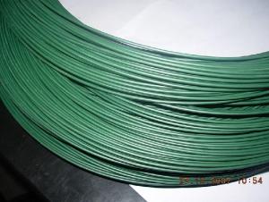
Galvanized Steel Wires For Pvc Coated Wires
- Ref Price:
-

- Loading Port:
- China Main Port
- Payment Terms:
- TT OR LC
- Min Order Qty:
- -
- Supply Capability:
- -
OKorder Service Pledge
OKorder Financial Service
You Might Also Like


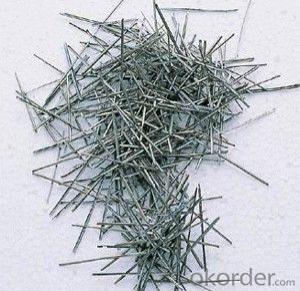

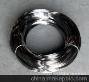
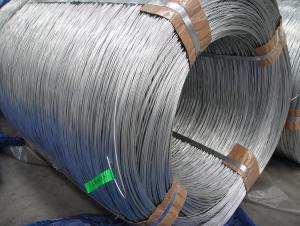
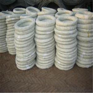
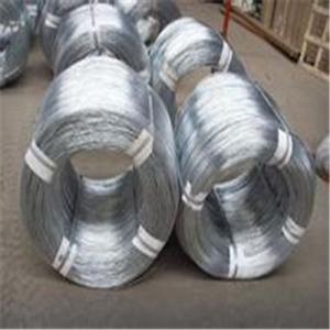
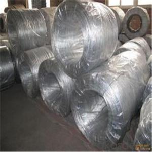
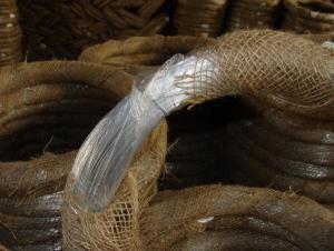
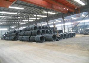
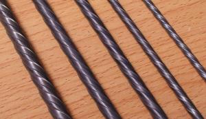
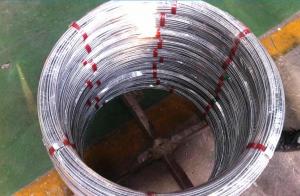
Hot Dip Galvanized Steel Wire
(1) Quality : Meet GB/T 343 standard and other requirements of relevant standards .
(2) Zinc Coating: Meet GB/T 15393 standard and other requirements of relevant standards .
(3) Raw Material : Wire rod ——1006 , 1008 , 1018 , Q195 , etc, and zinc with 99.995% purity.
(4) Tensile Strength Range
Size (mm) | Tensile Strength (mpa) |
0.15-1.60 | 290-550 |
0.65-1.60 | 400-550 |
1.61-6.00 | 400-1200 |
(5) Application : Used in wire mesh , artware , metal hose , binding for agriculture and construction , etc.
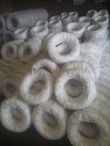
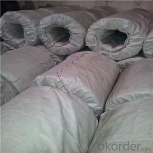
(6) Packing
Size (mm) | Coil Size | Spool Packing | Big Coil Packing | |
ID (mm) | OD (mm) | |||
0.15-0.26 | 6 inch | 1-14kg/spool |
|
|
0.27-0.60 | 8 inch | 1-100kg/spool |
|
|
0.61-1.60 | 12/14/16 inch | 1-100kg/spool | 250-400 | 400-770 |
1.61-6.00 |
| 14-500kg/spool | 450 | 800 |
508 | 840 | |||
(7) Zinc Coating
Meet GB/T 15393 standard.
Size (mm) | Weight of Zinc-Coating ( g/m2 ) | |||||||
A | AB | B | C | D | E | F | ||
A1 | B2 |
|
|
|
|
|
| |
≤0.25 |
|
| 30 | 20 | 18 |
|
|
|
>0.25-0.40 |
|
|
| 30 | 25 | 20 |
|
|
>0.40-0.50 |
|
|
|
| 30 | 20 |
|
|
>0.50-0.60 |
|
|
|
| 35 | 20 |
|
|
>0.60-0.80 | 120 | 110 |
|
| 40 | 20 |
|
|
>0.80-1.00 | 150 | 130 |
|
| 45 | 25 |
|
|
>1.00-1.20 | 180 | 150 |
|
| 50 | 25 |
|
|
>1.20-1.40 | 200 | 160 |
|
| 50 | 25 |
|
|
>1.40-1.60 | 220 | 180 |
|
| 50 | 35 | 30 |
|
>1.60-1.80 | 220 | 180 |
|
| 70 | 40 | 30 |
|
>1.80-2.20 | 230 | 200 |
|
| 80 | 50 | 40 |
|
>2.20-2.50 | 240 | 210 |
|
| 80 | 55 | 40 |
|
>2.50-3.00 | 250 | 230 |
|
| 90 | 70 | 45 |
|
>3.00-4.00 | 270 | 250 |
|
| 100 | 85 | 60 | 30 |
>4.00-5.20 | 290 | 270 |
|
| 110 | 95 | 70 | 40 |
>5.20-6.00 | 290 | 270 | 245 |
| 110 | 100 | 80 | 50 |
- Q: The wire is size 10AWG and will be to install a small fluorescent light in a closet. It is coming off of a typical electric outlet. I know someone who is witing it with commercial wire and I think it may be dangerous. Is it?
- that will be safe and it is OK ...not a problem ....
- Q: Theirs a green ground wire, a white neutral wire and for some reason 3 black wires.
- If the ceiling fan has three speeds, those would be wired to a 3 position switch as low, medium and high. Normally the wires would be labeled if they use the same color. If they aren't tagged, and you want to put in a speed control switch, you'll need to experiment; either at the fixture, or just wire them down to the wall switch and make your temporary connections there to see which wires go with which speeds (then TAG them!).
- Q: why do we use copper wires as connecting wires
- To use something as a connecting wire it should possess some qualities. First it should be a good conductor of electricity, that is it should have free electrons in its configuration. Secondly the substance should be malleable, that is it should be versatile enough to be stretched into wires. And lastly it should be available in abundance and should be economically feasible. As copper satisfies all the above prerequisites it is often used to make conducting wires.
- Q: I was re-wiring a light switch and a fan control knob and I accidentally cut a wire too short. This wire comes out the front of the fan dial and goes around to the back, connecting to another wire, thus placing a wire nut impossible. Can I just link the two ends together, then seal it with electrical tape? Or do I have to buy a new fan dial (which will cost $25, a cost I'm trying to avoid)? Will just the tape be safe enough?
- No they are NOT absolutely necessary, however the typical DIY'er does not have the skills or the tools to make a splice the old fashioned way. You can solder the two wires together after twisting them together in line and then cover them with shrink wrap. If you know what I am talking about and have the tools then wire nuts are not absolutely necessary, however if you do not have a clue how to do this or the necessary tools are then yes wire nuts are necessary. Just twisting them together and wrapping the connection with tape is not a good way to go.
- Q: I am installing an amp in my '04 Chevy crew cab truck and am running new wire for the speakers. I was able to get the fronts wired but when I broke into the back doors there is a feedthrough connector where I need to put the wires through. I am sure this connector contains the wires for my windows, door lights and the current speaker wires. My question is how do I get my new 18 gauge wires through to the speakers, am I missing something?Thanks in advance!!
- You can do a couple things, fish a stiffer wire through with your wire taped securely to it or , i hate to say this but you could tape two wires( your speaker wire, and a replacement wire) and cut one , and pull the two thru taped to the cut one. then reattach the cut ones ends to the replacement.Thats provided the one u might cut can move freely back and fourth.
- Q: My house is wired for surround sound. The wires coming out of the speakers holes are not labeled as far as i can tell but the wires that are coming out of housing that go into the back of the receiver are labeled 26,27,30,and 31. I cant tell which wires go to which speaker Front Left, Front Right, Rear left or Rear Right. Do these numbers mean anything?
- No. It should not be too hard to try hooking on speaker up at a time though and finding what runs to what. Then writing it down. Did the previous owner have a package of documenttion to pass on to you?
- Q: Can anyone tell me how to connect a older model ceiling fan in a new house... the fan itself has one white, one black , one red, one bare wire and a green wire. The wiring in the ceiling has one white, one black, one green and one copper wire. Thanks!
- If you look closely you will probably find the green wire in the ceiling is only attached to the junction box, connect all green and bare wires together, whites together and blacks and reds together, I'm sorry to tell you that you do not have enough wires present to control the fan and light separately, which is why they have chains, and you will have to use them. It sounds like the installation you have may allow the use of X10 modules for independent switching if it is needed. Be aware, your ceiling j-box may not be UL an NEC approved for fan installation. Ground wires are allowed to be either green or bare, and fixture ground wires are not required by ul to be copper, and all grounds should be attached together.
- Q: I am replacing a 2 wire circuit for a fan/light combo with a 3 wire fan/light combo switch. I ran a new 12/2 w/grnd to the switch box. I ran a 12/3 w/grnd to the ceiling box for the fan. I have a ceiling fan and light control switch that control light and fan separately. I can't figure out which wires go to what.
- Even though you gave an excellent explanation of the problem it is still too difficult to give you a proper answer without seeing the situation. If you have the money it is best for you to hire a pro. If not, then do you have a friend who knows a lot about wiring. The short you speak of is troubling and could be dangerous. You need to fix the problem soon. So get a pro or a qualified friend.
- Q: I am in the process of installing a new thermostat, but I ran into the problem: new thermostat has 4 ports W, Y, R and G. But the old thermostat has 5 wires: W, Y, G and B. I am not sure where B wire (black color) should go. Do I need to look for another thermostat that has a port for B wire?
- The black wire should be for ground. You and try to connect it without the black first to see if everything works ok, if it does tape off the black and tape it to the other wires. If not look at your UPM diagram and see which port is for ground and it should hook up with that wire. But I would double check with the heat pump wiring diagram to see what that black goes to and verify that wire with a multimeter.
- Q: The house was built in the 50's. Two wires are coming up from the switch and two wires are coming down from the top of the wall. I do not see a third wire. I attached the wall light wires left wires to left wires and right wires to right wires and light stayed on, when I moved the switch it threw the breaker. So I used may combination and the switch would not make the light work. It appears one wire may be white and one black. Help please!
- I think that 'ed' has given you good advice, if you know *nothing* about electrical wiring inside of the average home and about how two-way switching is wired. The two-way switch is designed for two wall switches at different locations from a common light or other electrical appliance to be able to turn the common appliance 'on' or 'off' independently from each other. If you have one of the boxes that a new two-way switch came in, it should show you, with usual wiring installed under the modern U.S. standard electrical code, which colored wires should be attached to which terminal connections at the INDIVIDUAL, separate switches. Ordinarilary the color coding for electrical wiring in the modern residence is 'white' is for the common 'ground'; 'black' is a 'hot - 115/120 volt-to-ground' wire; and the red should be a loop wire to the common appliance. When one of the wall switches is in the 'on' (up) position, and the other wall switch is in the 'off' (down) position, electrical power is furnished to the appliance. Changing the position of either of the wall switches, cuts off the power to the appliance. And changing the position of either ONE of the switches will supply power again. If you've done any wiring before, you should be able to figure it out, but follow what 'ed' suggested if you can, just to be sure.
Send your message to us
Galvanized Steel Wires For Pvc Coated Wires
- Ref Price:
-
- Loading Port:
- China Main Port
- Payment Terms:
- TT OR LC
- Min Order Qty:
- -
- Supply Capability:
- -
OKorder Service Pledge
OKorder Financial Service
Similar products
Hot products

Hot Searches
Related keywords

