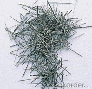
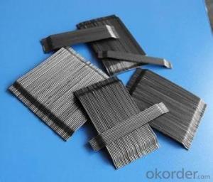
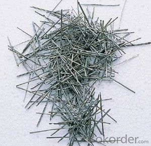
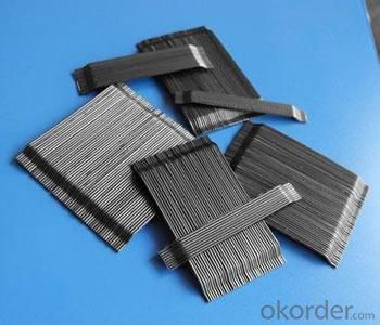
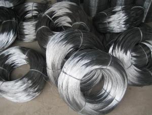
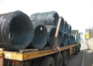
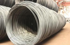
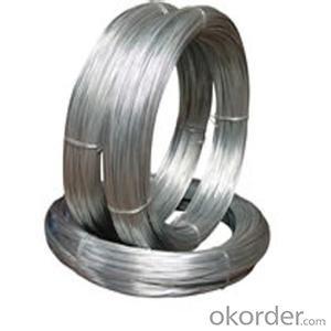
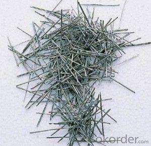
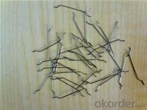
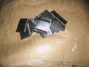
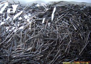
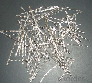
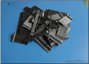
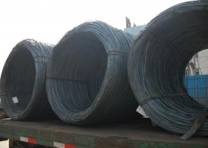
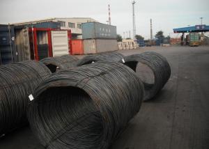
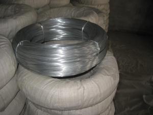
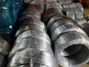
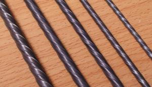
Steel fiber for concrete reinforcement from CNBM
- Loading Port:
- Tianjin
- Payment Terms:
- TT OR LC
- Min Order Qty:
- 1 m.t.
- Supply Capability:
- 9000 m.t./month
OKorder Service Pledge
Quality Product, Order Online Tracking, Timely Delivery
OKorder Financial Service
Credit Rating, Credit Services, Credit Purchasing
You Might Also Like
Quick Details
Place of Origin: Tianjin, China (Mainland)
- Material: Steel
Diameter(mm): 0.03-0.75mm
Length(mm): 6-60mm
Aspect ratio(L/D): 30-80
Tensile strength(Mpa): >1200Mpa
Packaging & Delivery
| Packaging Details: | 20 kg/Bag,50 bags/Pallet or 1,000kg/ Bulk Bag |
|---|---|
| Delivery Detail: | Within 15 days after receiving deposit or original L/C at sight |
Product Description
| Diameter | 0.5mm, 0.6mm, 0.75 mm, 0.8mm, 0.9mm | ||
| Length | 30mm, 35mm, 50mm, 60mm | ||
| Aspect Ratio | 60, 65,80 | ||
| Tensile strength | 1200 MPa | ||
| Type | Cold drawn Steel Fiber | ||
| End | Hooked-end Steel Fiber | ||
| Glued/Loose | Glued Steel Fiber | ||
| Bending Angle | 45°(min.30°) | ||
| Usage & Performance | Floor:Trafficked areas and Industrial floors | ||
| Shotcrete :Slope stabilization and Final lining | |||
| Precast concrete:Pipe and Railway sleepers | |||
| Packing | Standard Export Pallet Packing | Bag Packing | 20 kg/Bag,50 bags/Pallet |
| Bulk Packing | 1,000kg/ Bulk Bag | ||
| Loading Quantity | 20’GP | 20-25 Tonne/Tonnes | |
| 40’GP | 25-27 Tonne/Tonnes | ||
| 40’HQ | 25-27 Tonne/Tonnes | ||
| MOQ | 1 kg for trial order | ||
| Supply Ability | 10,000 Tonne/Tonnes per Year | ||
| Payment Terms | T/T or L/C at sight | ||
| Delivery Time | Within 15 days after receiving deposit or original L/C at sight | ||
| Certification | ISO9001:2000, CE, | ||
- Q: Hi there,I have a very old house which only has 2 wires (1 white, 1 black) coming out of the wall.The ceiling fan / light has 2 red wires, 1 black, 1 green.What is right way to wire for this to operate?Thanks,
- Most fans have a wiring schematic and this will tell you how to wire it. Normally black is the power, green is a ground, which you don't have, and as for the red wires I'm not sure. Is this a new fan or one that has been used before. In the USA we have a white wire which is a neutral. I'm puzzled about the two red wires, these may have been added at a later date. If your in a country that has 240 volts then this may be an explanation. Regards, Dale
- Q: so i got a few questions. on my 2000 chevy cavalier i got my audio system upgraded but toke it to a shop to get done i am ready to hook up a amp and woof but wanna do it my self to save a few hundred bucks as i was observing my car where to put stuff at i notice a blue wire that is going from where it looks like from my radio to my fuse box on the driver side and is hooked up to a fuse. what is that? and if its the remote wire can i hook up the remote wire for the amp with that blue wire to or is that to much?
- There shouldnt be a wire going to your fuse box... They should have reused the stock harness and all of its connections. There should be a remote wire that comes off the deck and it is generally a Blue wire, but its never long enough to reach the fuse box. I am guessing thats a power wire. You will need to run a set of preouts and a remote wire from the head unit to the amp. You will also need to wire power to the amp.
- Q: Need wiring diagram or manual
- Bard Air Conditioner
- Q: i need to know how to rewire it to make it fire the only wire that is still there is the one that runs to the distributor cap all the other wires are gone is it sopose to wire to the key please help
- find direction from a technitian
- Q: Anyone know which wire behind the navigation unit is the brake wire? I THINK it's pink, but there are multiple pink wires behind the navigation unit.Thoughts?
- Are okorder 's outlander section for a posts on how to disable.
- Q: I'm trying to install a ceiling fan but I'm having trouble with the wiring. Coming out of the fan I've got a black, white, black and white striped, and a green wire. coming out of the cieling i've got a black, a white and a red wire.The fan's green wire is connected to the bracket as a ground, so that's out of the way. It's the other wires that confuse me. I've tried, white to white, black to black, and BW striped to red, but that didn't do anything.Any ideas? Thanks.
- You would need a meter to check those wires coming out of the ceiling...usually 3 wire cable (black, red, and white) are used for a 3 way switch which can be turned on and off at 2 separate location (example:at both ends of a staircase)..If this is your situation, you will need only 2 wire cable (black and white) on a switch..you didn't mention whether you have a lighted fan or not..If so, the black w/white stripe would be for the light...just one more thing, make sure your room switch is on when testing it...
- Q: I have a 3 wire source I want to connect it to a switch on/off and then make it 2 wire to the light
- If you have black red and white, it could be wired for a three way switch, best to call an electrician as this is too complicated to write the testing procedures. If the wires are black white green more than likely the green is ground. Simple test with power on black to white 110v, black to green 110v, white to green 0v. If this is the case, ground the switch using the green wire to the ground terminal on the switch, whites from the power source is connected to white going to light using a wire nut or other approved method, both blacks are connected to the two brass terminal screws on the switch, it does not matter which terminals you use, just make sure when you are installing the switch back into the work box that off is down. Good luck and if you are in any way unsure call a licensed electrician, they'll only charge a service fee plus materials for a job that small.
- Q: I'm doin this thing where I need to connect some wires and one part uses Apple iPod headphones. Inside those wires, they have insulation. I burnt the wires so the insulation would not be in the way. Will the wires still conduct the electricity? Or will I just need to find some other headphones without insulation to do this with?
- It depends. If the wires themselves got oxidized when you burned the insulation off, they will not conduct electricity as well as they did before. On the other hand, if you burned them in a way that converted the non-conducting plastics (organic polymers) into graphite (pure carbon) the wires might conduct a little better (because graphite conducts electricity). When you say there is insulation inside the wires, you may be confused. Some small electrical wires contain threads braided or twisted in with the fine copper wires to increase strength. These threads are usually non-conductors so, technically, I guess you could call them insulators but they are not in there to prevent one wire from making electrical contact with another wire. You can check if the wire still conducts elecricity with a battery and the bulb out of a flashlight. good luck
- Q: anybody got a diagram or instructions on how to wire an amp wiring kit in a 1999 audi a4
- run okorder /
- Q: What's the metal wire fabric?Such as title
- Because the implant metal wire fabric because of the overall color bright, if there is a light metal, can reflect the specific metallic luster. But note that not only the characteristics of metal wire fabric in metallic luster, and anti-static, with anti radiation, more conducive to regulate all aspects of the body
Send your message to us
Steel fiber for concrete reinforcement from CNBM
- Loading Port:
- Tianjin
- Payment Terms:
- TT OR LC
- Min Order Qty:
- 1 m.t.
- Supply Capability:
- 9000 m.t./month
OKorder Service Pledge
Quality Product, Order Online Tracking, Timely Delivery
OKorder Financial Service
Credit Rating, Credit Services, Credit Purchasing
Similar products
Hot products
Hot Searches
Related keywords
