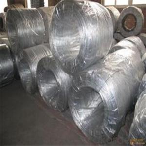
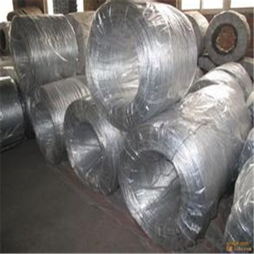
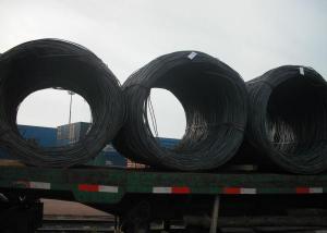
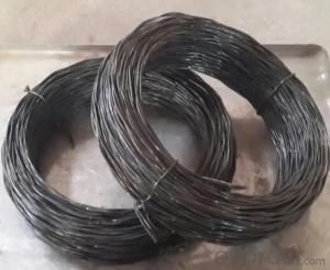
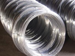
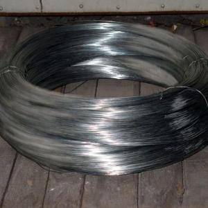
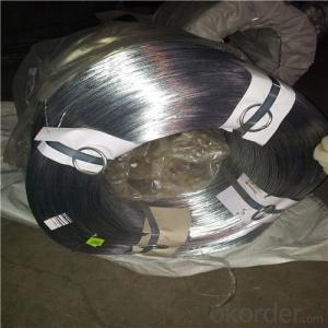
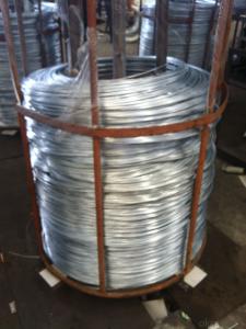
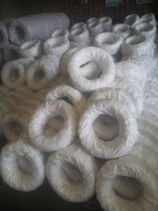
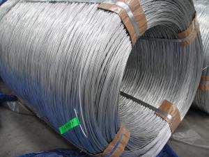
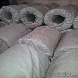
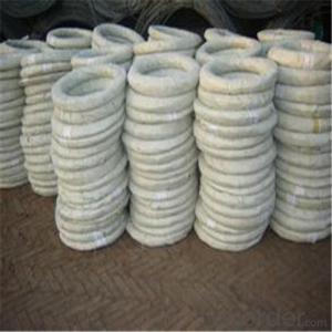
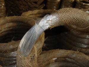
Best Quality Galvanized Steel Wires For Pvc Coated Wire
- Loading Port:
- China Main Port
- Payment Terms:
- TT OR LC
- Min Order Qty:
- -
- Supply Capability:
- -
OKorder Service Pledge
OKorder Financial Service
You Might Also Like
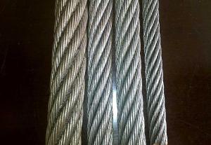
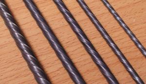
Galvanized Wire/Galvanized Steel Wire/ Gavanized Iron Wire
Diatmeters:0.15mm-6mm
Application | Weaving, braiding, fencing, cable armoring, knitting, tie wire, for redrawn, for binding or forming etc. |
Material | low carbon steel wire |
Diameter | 0.15mm~6.00mm |
Tensile strength | 350-500MPA, or higher |
Zinc coating | Min 12g/m2, min 25g/m2, min 200g/m2,min 300g/m2,610g/m2 |
Surface treatment | Hot dipped or electro galvanized |
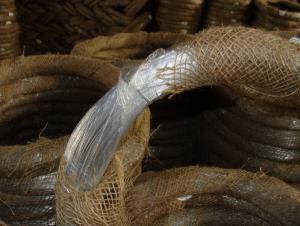
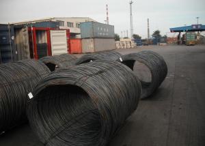
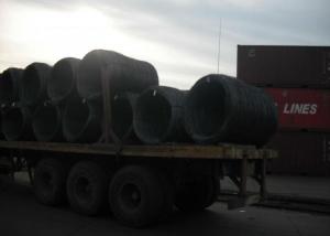
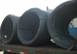
Packing | On spools In small coils of 25-50kg/coil, 10kg/coil In rosette coil of 100-800kg/coil |
Standard | ASTM 641, EN10257-1& EN10244-2 |
All can be produced according to customers’ requirements.
- Q: I am replacing a regular light switch with a more fashionable looking design. When I took out the old light switch there was a red and a black wire attached. I am used to white and black. Which wire is considered the white wire when I am wiring this switch?
- It depends on how they ran the power to the switch. In a standard circuit, white is the neutral. In the switch leg, where you are working, there is no neutral. They can use any wires for a switch except green. You had seen black and white because those are the colors in a 2 conductor Romex cable. This may be a 3 conductor which has red, white, and black. In any case, each of the 2 loose wires go on one of the the brass screws of the switch, and the ground if there is one goes on the green. Some electricians will tape the white wire if it's used in a switch leg to indicate that it's not a neutral. Hope this helps.
- Q: What's the thickness, or measurement for the last or thickest wire?
- they change your wire according to how much your teeth have shifted around, so it just depends. the ortho needs to adjust the size of the wire due to your teeth straightening out and making sure the wire(s) are at a correct length. its really not that thick of a wire, so don't worry about it. :D
- Q: I have two black wires running to a light switch that I need to extend about a foot. I cannot identify the hot wire because both wires are black and I have no white wire. Can I cap off both wires and then test each with a voltmeter? If the circuit is not complete, will the hot wire still be live?
- ok, a light switch is different then a outlet plug. the black wire is the hot wire and comes in to one side if the switch and goes out the other side. the switch just open the circuit to turn off the light or closes the circuit to turn it on.
- Q: Wire runs from breakers to a wall outlet along the garage wall
- you need ot use ordinary romex of a guage that will serve the power draw you intend it for and a breaker to match. i fyou already have breakers you intend to use, be sure to use the proper guage of romex so as to not have an electricsal fire. furhter, you usually have to enclose romes, it cannot be exposed along a wall if it comes from the breakerbox. you can get romex in conduit at home depot, etc.
- Q: Wiring together 200 + different colored LEDs. Voltage per LED ranges from 2.5 - 3.6. What is the best way to go about wiring them together and what type of power source should i use?
- You have the voltage requirements for the LEDs, but a current requirement (and hence a measure of power consumed) would be useful. Find this out. Regarding power source, a battery that satisfies the requirements below will suffice... You have a choice of wiring in series or parallel. Parallel means effectively a branch of wire per LED (voltage over each LED is battery voltage; current into each is battery current divided by number of LEDs), while series means one long wire going through them all (battery current goes through them all, voltage over each is battery voltage divided by number of LEDs). Depends on the presentation you want, and what you are using them for. When you decide which wiring type you want to use, just make sure the wires you buy are sufficient for carrying whatever current you predict will be flowing through each. Have fun :p
- Q: I have a audiofonics adf-240 and I want to wire it to 1 ohm
- To wire an amp to a certain ohm load depends on the speakers..... not the amp .... the amp just has to be stable at the ohm load you wire the speakers to.....but there's your next problem , that amp is NOT 1 ohm stable.... Its 2 ohm stereo and 4 ohm bridged stable.
- Q: I recently bought a set of DT Moto emergency lights for my pickup and after installing them i found when i went to wire them to my battery the wire was too short. I didn't install the grille lights just the visor. Could i cut wires from the grille set and wire them to extend the visor light wire?
- I'm looking online to find out what DT Moto lights are. Ok, I see what they are. I didn't know the brand name. LED lights in general are not high current, so they probably use lamp cord. I want to explain something to you about polarity. Electronic circuits are sensitive to the polarity of the DC electricity. The positive (+) and the negative (-) connections must be observed. So many people have absolutely no clue about this. There are just two wires. But if you extend them, you have a 50-50 chance of wiring correctly or incorrectly. There is only one allowable way. If wrong, it WON'T work, and probably will blow up the circuitry. So connection to battery or cigarette lighter plug is extremely important not to reverse the polarity. If just the LED lights got reversed, they wouldn't light, but they wouldn't be injured. Just reverse the wiring. But to the 12 volt source, polarity can't be wrong. Not for an instant. If you look closely at the insulation, you will see that one wire has smooth insulation, and one wire either has milti-ribbed insulation, or a single rib down the side. If you extend wiring, make sure to connect smooth to smooth and ribbed to ribbed. Wires should be soldered with electronic solder and the joints covered with heat shrink tubing. No crimped barrel connectors, or twisted bare wires with tape, or house wiring wire nuts. These methods all beg for failure. I don't know about robbing wire from one place and connecting to another. Is the one wire actually too long? You'll never need it? I guess you could take it. But me personally, I'd go get some wire from a lamp store. Match the wire conductor gauge (size), not the insulation size. Most lamp cord is 18 gauge. Some is 16 gauge. You can get 14 gauge or even 12 gauge. Thicker is a smaller number. Places that install car audio systems often have/sell thicker lamp cord. Have I told you enough?
- Q: Can we use pilot wire protection to protect overhead line, and which country use this scheme ?
- Pilot wire protection can be used anytime anywhere. The question is not where it is used but why, and is it required. Pilot wire protection provides better discrimination of fault location, than, say, an impedance or distance relay. If the zones are too close, pilot wire may be the only feasible solution. .
- Q: how do i connect ignition wire from fuse box to cd player?
- find the positive fuse by using a test light on the fuses, when the ignition is on the light your using will light up when the ignitions off it should not light up on the test light, once thats done connect a wire from the back of that fuse behind the fuse box to the terminal run the wire to the stereo wire you need to connect to, twist the wires together use decent electrical tape aroung the join to make sure the bare join does not touch anything else on the car. hope this helps.
- Q: But when I look closely (you can't see it in the picture unfortunately) there are some tiny wisps of the coiled copper wire that looks as if it could have been connected to the pulled wire. I'm not sure.How do I connect the wires to make the headsets work again?If you guys need more pictures, please tell me.Thanks in advance!
- If the twine is broken (open-circuit), rewiring it would artwork. the wonderful thank you to rewire it would be to strip the wires and solder them back at the same time. i might additionally attempt to untwist the twine as much as conceivable till now attempting this. in case you do not have get entry to the soldering kit, attempt twisting the wires back at the same time tightly and wrapping with electric tape. in case you ought to do it this style, it is going to probable no longer postpone for extremely long. reliable success!
Send your message to us
Best Quality Galvanized Steel Wires For Pvc Coated Wire
- Loading Port:
- China Main Port
- Payment Terms:
- TT OR LC
- Min Order Qty:
- -
- Supply Capability:
- -
OKorder Service Pledge
OKorder Financial Service
Similar products
Hot products
Hot Searches
Related keywords
