


IPE/IPEAA beams for sale
- Ref Price:
-

- Loading Port:
- Shanghai
- Payment Terms:
- TT OR LC
- Min Order Qty:
- 25 m.t.
- Supply Capability:
- 10000 m.t./month
OKorder Service Pledge
OKorder Financial Service
You Might Also Like
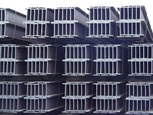
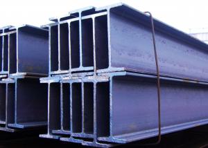
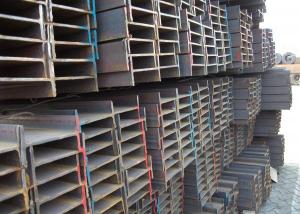
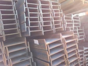
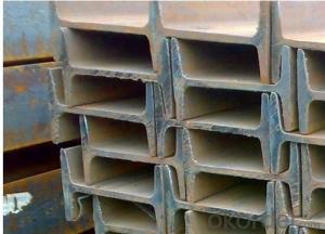
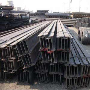
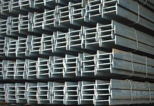
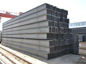
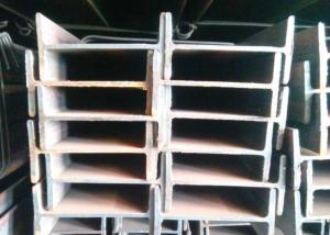
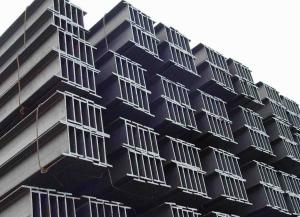
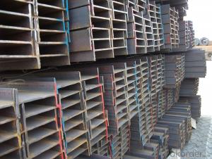
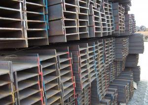
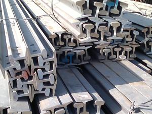
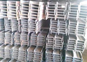
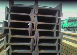
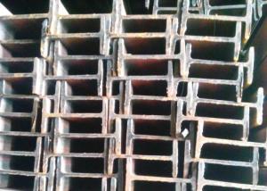
Specifications of IPE/IPEAA Beam Steel
1. Product name: IPE/IPEAA Beam Steel
2. Standard: EN10025, GB Standard, ASTM, JIS etc.
3. Grade: Q235B, A36, S235JR, Q345, SS400 or other equivalent.
4. Length: 5.8M, 6M, 9M, 10M, 12M or as your requirements

Section | Standard Sectional Dimensions(mm) | ||||
h | b | s | t | Mass Kg/m | |
IPE80 | 80 | 46 | 3.80 | 5.20 | 6.00 |
IPE100 | 100 | 55 | 4.10 | 5.70 | 8.10 |
IPE120 | 120 | 64 | 4.80 | 6.30 | 10.40 |
IPE140 | 140 | 73 | 4.70 | 6.90 | 12.90 |
IPE160 | 160 | 82 | 5.00 | 7.40 | 15.80 |
IPE180 | 180 | 91 | 5.30 | 8.00 | 18.80 |
IPE200 | 200 | 100 | 5.60 | 8.50 | 22.40 |
IPE220 | 220 | 110 | 5.90 | 9.20 | 26.20 |
IPE240 | 240 | 120 | 6.20 | 9.80 | 30.70 |
IPE270 | 270 | 135 | 6.60 | 10.20 | 36.10 |
IPEAA80 | 80 | 46 | 3.20 | 4.20 | 4.95 |
IPEAA100 | 100 | 55 | 3.60 | 4.50 | 6.72 |
IPEAA120 | 120 | 64 | 3.80 | 4.80 | 8.36 |
IPEAA140 | 140 | 73 | 3.80 | 5.20 | 10.05 |
IPEAA160 | 160 | 82 | 4.00 | 5.60 | 12.31 |
IPEAA180 | 180 | 91 | 4.30 | 6.50 | 15.40 |
IPEAA200 | 200 | 100 | 4.50 | 6.70 | 17.95 |
Applications of IPE/IPEAA Beam Steel
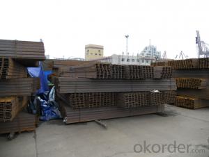
IPE/IPEAA Beam Steel are widely used in various construction structures, bridges, autos, brackets, mechanisms and so on.
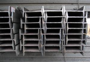
Packing & Delivery Terms of IPE/IPEAA Beam Steel
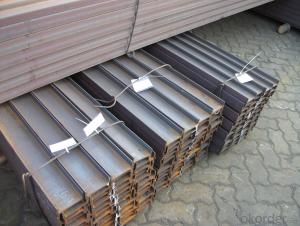
1. Package: All the IPE/IPEAA Beam Steel will be tired by wire rod in bundles
2. Bundle weight: not more than 3.5MT for bulk vessel; less than 3 MT for container load
3. Marks:
Color marking: There will be color marking on both end of the bundle for the cargo delivered by bulk vessel. That makes it easily to distinguish at the destination port.
Tag mark: there will be tag mark tied up on the bundles. The information usually including supplier logo and name, product name, made in China, shipping marks and other information request by the customer.
If loading by container the marking is not needed, but we will prepare it as customer request.
- Q: Are steel I-beams recyclable?
- Indeed, steel I-beams can be recycled. Thanks to its durability and high scrap value, steel is widely considered one of the most recycled materials globally. Once steel I-beams reach the end of their useful lifespan, they can undergo recycling and be transformed into new steel products. The recycling procedure consists of melting down the steel to eliminate any impurities, after which it is fashioned into new I-beams or other steel products. By recycling steel I-beams, not only are we conserving natural resources, but we are also reducing the energy consumption and carbon emissions linked to the production of new steel from raw materials.
- Q: Can steel I-beams be used in high-rise buildings?
- Yes, steel I-beams can be used in high-rise buildings. In fact, steel I-beams are commonly used in high-rise building construction due to their strength, durability, and load-bearing capabilities. The I-shape of the beam provides excellent structural support, allowing them to span long distances and carry heavy loads. Additionally, steel I-beams can be easily fabricated and assembled, making them a cost-effective choice for high-rise construction projects. Their versatility and ability to withstand high pressures and forces make them a popular choice for constructing the skeletal framework of high-rise buildings.
- Q: How do you calculate the section modulus of a steel I-beam?
- The section modulus of a steel I-beam can be calculated by taking the moment of inertia of the cross-sectional area of the beam and dividing it by the distance from the neutral axis to the top or bottom of the beam. This calculation helps determine the beam's resistance to bending and is an important factor in structural engineering analysis.
- Q: How do steel I-beams contribute to the overall sustainability of a structure?
- Steel I-beams play a vital role in enhancing the sustainability of structures in several ways. To begin with, steel is a highly recyclable material, allowing I-beams to be produced and recycled using recycled steel. This reduces the demand for new steel production and lessens the environmental impact of extracting and processing raw materials. Furthermore, steel I-beams are renowned for their strength and durability. By incorporating steel I-beams in construction, buildings can be designed to have a longer lifespan, reducing the need for frequent repairs or replacements. This extended lifespan helps conserve resources and minimize waste. In addition, energy efficiency is another aspect of sustainability that steel I-beams contribute to. Steel is an excellent conductor of heat, enabling the efficient distribution of heat throughout a structure. Consequently, energy consumption for heating and cooling purposes can be reduced, resulting in lower energy bills and a smaller carbon footprint. Moreover, steel I-beams are lightweight yet sturdy, allowing for more efficient transportation and installation. The reduced weight leads to lower fuel consumption during transportation, while the ease of installation saves time and labor costs. Overall, this enhances the sustainability of the construction process by reducing energy use and associated emissions. Lastly, steel I-beams offer design flexibility, enabling more creative and innovative architectural designs. This flexibility leads to more efficient use of space, reduced material waste, and improved functionality, all of which contribute to the overall sustainability of the structure. To conclude, steel I-beams significantly contribute to the overall sustainability of structures through their recyclability, strength and durability, energy efficiency, lightweight design, and design flexibility. By incorporating steel I-beams into construction projects, we can create environmentally friendly and sustainable buildings that minimize resource consumption, waste generation, and energy use.
- Q: What are the potential cost savings associated with using steel I-beams?
- There are several potential cost savings associated with using steel I-beams in construction projects. Firstly, steel I-beams are known for their high strength-to-weight ratio, meaning they can carry heavy loads while using less material compared to other alternatives. This leads to cost savings in terms of reduced material costs and transportation expenses. Additionally, steel I-beams are durable and resistant to decay, pests, and fire. This means they have a longer lifespan compared to other materials, resulting in lower maintenance and replacement costs over time. Moreover, steel I-beams are relatively quick and easy to install, especially when compared to traditional construction methods. This can lead to significant time savings, which in turn can translate into reduced labor costs. Furthermore, steel is a highly recyclable material. If the need arises to remodel or demolish a structure that uses steel I-beams, the beams can be efficiently recycled and reused. This not only reduces waste but also potentially lowers the overall environmental impact of the project. Lastly, steel I-beams are readily available in standard sizes, which can help streamline the construction process and minimize the need for custom fabrication. This standardization can result in cost savings due to reduced lead times and increased efficiency in production. In summary, the potential cost savings associated with using steel I-beams include reduced material and transportation costs, lower maintenance and replacement expenses, quicker installation times, recyclability, and increased production efficiency.
- Q: How do steel I-beams perform in areas with high salinity or corrosive environments?
- Steel I-beams can perform well in areas with high salinity or corrosive environments, particularly if they are properly protected and maintained. High salinity and corrosive environments, such as coastal regions or industrial areas, can accelerate the corrosion process and potentially compromise the structural integrity of steel. To mitigate the effects of high salinity and corrosion, steel I-beams are often coated with protective materials such as galvanized coatings, epoxy coatings, or specialized paint systems. These coatings act as a barrier, preventing direct contact between the steel and the corrosive elements. Regular inspections and maintenance are also essential to identify and address any signs of corrosion early on. However, it is important to note that even with protective coatings, the lifespan of steel I-beams in high salinity or corrosive environments may be reduced compared to those in less corrosive environments. The severity of the environment, the quality of the coatings, and the maintenance practices all play a crucial role in determining the performance and longevity of steel I-beams in such conditions. In particularly harsh environments, alternative materials such as stainless steel or fiberglass-reinforced polymers (FRP) may be considered as they are inherently more resistant to corrosion. These materials offer extended durability and are often used in marine structures or other applications where corrosive conditions are prevalent. Overall, steel I-beams can still be a viable option in areas with high salinity or corrosive environments, provided that appropriate protective measures are taken and regular maintenance is carried out. Consulting with structural engineers or corrosion specialists can help determine the most suitable approach to ensure the long-term performance and safety of steel I-beams in such conditions.
- Q: No. 10 I-beam for the main beam, 10 channel steel by the wall as auxiliary beam reinforcement, attic construction problems
- A loft is a room at the bottom of a house slope.
- Q: Can steel I-beams be used in sports stadiums?
- Steel I-beams are indeed suitable for use in sports stadiums. They are widely utilized in the construction of these venues due to their robustness and endurance. By withstanding heavy loads and offering structural integrity, these beams can be incorporated into the stadium's roof, seating sections, and other vital structural elements. The utilization of steel I-beams is especially favored because they possess the ability to span long distances independently, thereby eliminating the need for supplementary supports. This flexibility allows for versatile and open design possibilities in sports stadiums. Furthermore, the adaptability of steel I-beams enables them to be tailored and fabricated to satisfy the precise design requisites of the stadium, assuring the safety and stability of both spectators and athletes.
- Q: What are the potential drawbacks or limitations of using steel I-beams?
- One potential drawback of using steel I-beams is their weight, which can make installation and transportation more challenging compared to lighter materials. Additionally, steel is prone to corrosion and requires regular maintenance to prevent rust and ensure its structural integrity. Another limitation is that steel I-beams have a high thermal conductivity, making them susceptible to temperature variations and potentially causing expansion or contraction. Finally, steel I-beams can be relatively expensive compared to other building materials, which may impact the overall cost of a construction project.
- Q: How do you calculate the shear capacity of a steel I-beam?
- The shear capacity of a steel I-beam can be calculated by determining the shear force that the beam can resist without causing failure. This can be calculated using the equation V = 0.6 * A * Fy, where V is the shear capacity, A is the area of the web of the beam, and Fy is the yield strength of the steel used in the beam.
Send your message to us
IPE/IPEAA beams for sale
- Ref Price:
-
- Loading Port:
- Shanghai
- Payment Terms:
- TT OR LC
- Min Order Qty:
- 25 m.t.
- Supply Capability:
- 10000 m.t./month
OKorder Service Pledge
OKorder Financial Service
Similar products

Hot products
Hot Searches
Related keywords

