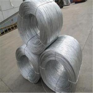
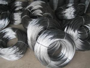
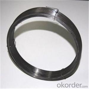
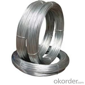
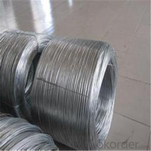
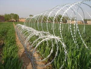
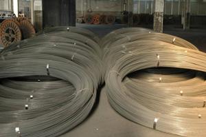
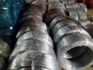
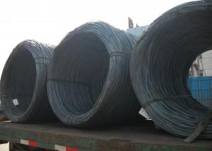
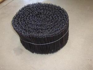
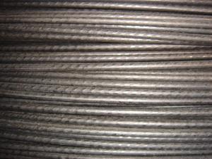
High Quality Galvanized Iron Wires For Gabion
- Loading Port:
- China Main Port
- Payment Terms:
- TT OR LC
- Min Order Qty:
- -
- Supply Capability:
- -
OKorder Service Pledge
OKorder Financial Service
You Might Also Like
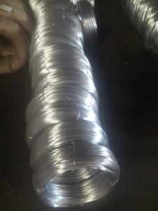
Galvanized Wire/Galvanized Steel Wire/ Gavanized Iron Wire
Diatmeters:0.15mm-6mm
Application | Weaving, braiding, fencing, cable armoring, knitting, tie wire, for redrawn, for binding or forming etc. |
Material | low carbon steel wire |
Diameter | 0.15mm~6.00mm |
Tensile strength | 350-500MPA, or higher |
Zinc coating | Min 12g/m2, min 25g/m2, min 200g/m2,min 300g/m2,610g/m2 |
Surface treatment | Hot dipped or electro galvanized |
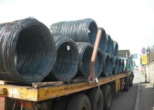
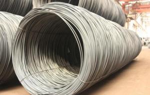
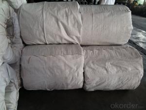
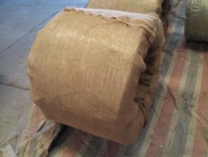
Packing | On spools In small coils of 25-50kg/coil, 10kg/coil In rosette coil of 100-800kg/coil |
Standard | ASTM 641, EN10257-1& EN10244-2 |
All can be produced according to customers’ requirements.
- Q: but it says there are three Pink wires. There's not even three pink wires coming out of the car.The chassis/clip has been removed (by previous owner) and all that is left is the wires. All that is needed is a list of the colors and what they go to. Thanks.
- Try going to the radio manufacture's website. Some of them have the owner's manuals online with the diagrams in them.
- Q: why is neutral wire.explain plz
- The neutral is held at ground, to give a path for the current to return. The ground is for safety.
- Q: how are lights grounded on a car? Seems like all the wires to the light have electricity running to them.
- Is somebody suppose to know what light you're talking about?
- Q: My house is wired for surround sound. The wires coming out of the speakers holes are not labeled as far as i can tell but the wires that are coming out of housing that go into the back of the receiver are labeled 26,27,30,and 31. I cant tell which wires go to which speaker Front Left, Front Right, Rear left or Rear Right. Do these numbers mean anything?
- No. It should not be too hard to try hooking on speaker up at a time though and finding what runs to what. Then writing it down. Did the previous owner have a package of documenttion to pass on to you?
- Q: what wires are my speaker wires going to and coming from the factory amp and how do i hook them up please help i drive a 96' ford exploder
- 1996 Ford Explorer Car Stereo Radio Wiring Diagram Car Radio Constant 12v+ Wire: Green/Violet Car Radio Switched 12v+ Wire: Yellow/Black Car Radio Ground Wire: Black/Light Green Car Radio Illumination Wire: Light Blue/Red Car Stereo Dimmer Wire: N/A Car Stereo Antenna Trigger: Orange/Blue Car Stereo Amp Trigger Wire: Blue (If Equipped) Car Stereo Amplifier Location: N/A Front Speakers Size: N/A Front Speakers Location: N/A Left Front Speaker Positive Wire (+): Orange/Light Green Left Front Speaker Negative Wire (-): Light Blue/White Right Front Speaker Positive Wire (+): White/Light Green Right Front Speaker Negative Wire (-): Dark Green/Orange Rear Speakers Size: N/A Rear Speakers Location: N/A Left Rear Speaker Positive Wire (+): Gray/Light Blue Left Rear Speaker Negative Wire (-): Tan/Yellow Right Rear Speaker Positive Wire (+): Orange/Red Right Rear Speaker Negative Wire (-): Brown/Pink
- Q: How could you relate greater wire length resulting in greater resistivity to the context of home
- Greater wire length will certainly give you a higher resistance. Since heat is measured in watts, and watts (W) =I^2R, where I=Current and R= resistance, then if you double the resistance of a wire (by making it twice as long) you also double the ammount of watts lost in the wire. Since watts equates to heat, this ammount of heat will make the wire hotter. If you use an extension lead, and wind it round a drum, it can get very hot indeed.
- Q: Does anyone know where i can buy them? I need new ones because my crazy cat chewed up two of the wires lol =#92;
- Buy some speaker wire and electrician's tape and splice new wire in the area where the old wire is chewed. Make sure you don't cross positive with negative. This way, you don't have to worry about getting the right connections, and it will be inexpensive.
- Q: How can u do a wire transfer? Is there anything extra that is needed to do this? Are you able to make a wire transfer from your home computer?
- A wire transfer is that exact same as sending cash. As soon as it is gone. It is gone. The bank can not protect you. I suggest using a credit card. If they will only accept wire transfer as payment I would be very thorough on my research into the company and know exactly who I was dealing with. I would pay the extra fees via pay-pal where you have some protection. If he is a fraud and you wire money, you are out the money unless you hire an attorney to help you get it back which will probably cost you more than the 8k. I'd buy local if you can in this instance.
- Q: how to wire a receptacle with 6 wires?
- use 3 wire nuts and 3 jumpers, color to color and then connect the others together. Black wire to the dark screw, white color to the silver screw and the green to the ground connection. If this does not make sense to you contact a local qualified professional electrician to do the work.
- Q: Has anyone ever used welding wire in their car audio setup?Is it more flexible or less than other car power wire? Is this a big problem?Is it a good or bad jacket?Would you use it again?I am looking at buying some welding wire from weldingsupply because it is .81 per foot. I would love to know if anyone has done this before and what they thought. The wire i am looking at is 4 gague.
- It is actaully the exact same wire as the auto manufacturs use.... just bigger gauge is all. Edit... I see most people don't see it as possible.... well let me ask you this, How different do you think copper wire can be from another copper wire? If you really wanted too you can use speaker wire for power wire.... because at the end of the day wire is wire!
Send your message to us
High Quality Galvanized Iron Wires For Gabion
- Loading Port:
- China Main Port
- Payment Terms:
- TT OR LC
- Min Order Qty:
- -
- Supply Capability:
- -
OKorder Service Pledge
OKorder Financial Service
Similar products
Hot products
Hot Searches
