
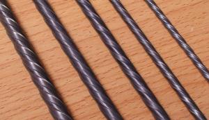
Innovative rebar steel prices steel fiber
- Ref Price:
-

- Loading Port:
- Tianjin
- Payment Terms:
- TT OR LC
- Min Order Qty:
- 1 m.t.
- Supply Capability:
- 10000 m.t./month
OKorder Service Pledge
Quality Product, Order Online Tracking, Timely Delivery
OKorder Financial Service
Credit Rating, Credit Services, Credit Purchasing
You Might Also Like


Quick Details
Place of Origin: Tianjin, China (Mainland)
Model Number: 0.5
Material: Steel
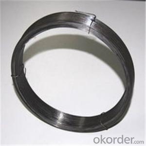
Production Process: Cold drawn
Fiber Lengh: 30
Type: 1
Compressive Strength: >1200MPa
Aspect ratio: 60
Standard: ASTM A820M-11
Section Shape: Circular
Application: Concrete Reinforcement
Product Application: Tunnel
Packaging & Delivery
| Packaging Details: | 20 kg/Bag,50 bags/Pallet or 1,000kg/ Bulk Bag |
|---|---|
| Delivery Detail: | 1 Month |
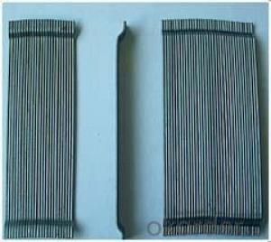
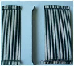
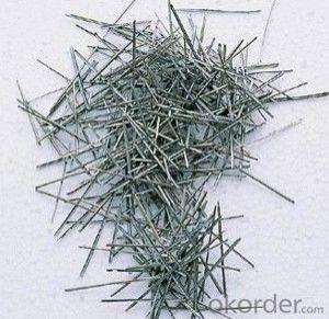
Product Description
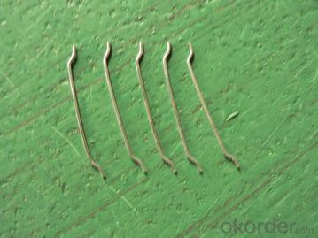
| Diameter | 0.50 | mm | 0.02 | in |
| Length | 30.00 | mm | 1.18 | in |
| Aspect Ratio | 60 | |||
| Tensile strength | 1200 MPa | |||
| Type | Cold drawn Steel Fiber | |||
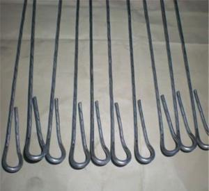
| End | Hooked-end Steel Fiber | |||
| Glued/Loose | Glued Steel Fiber | |||
| Bending Angle | 45°(min.30°) | |||
| Usage & Performance | Floor:Trafficked areas and Industrial floors | |||
| Shotcrete :Slope stabilization and Final lining | ||||
| Precast concrete:Pipe and Railway sleepers | ||||
| Packing | Standard Export Pallet Packing | Bag Packing | 20 kg/Bag,50 bags/Pallet | |
| Bulk Packing | 1,000kg/ Bulk Bag | |||
| Loading Quantity | 20’GP | 20-25 Tonne/Tonnes | ||
| 40’GP | 25-27 Tonne/Tonnes | |||
| 40’HQ | 25-27 Tonne/Tonnes | |||
| MOQ | 1 kg for trial order | |||
| Supply Ability | 10,000 Tonne/Tonnes per Year | |||
| Payment Terms | T/T or L/C at sight | |||
| Delivery Time | Within 15 days after receiving deposit or original L/C at sight | |||
| Certification | ISO9001:2000, CE, | |||
| Product | Diameter | Length mm/in | Aspect Ratio | Type | Packing |
| G-6030 | 0.5 mm (0.0197 in) | 30 mm (1.1811 in) | 60 | Glued | 20 kg/Bag, or 1,000kg/ Bulk Bag |
| G-6535 | 0.55 mm (0.0217 in) | 35 mm (1.3780 in) | 65 | Glued | 20 kg/Bag, or 1,000kg/ Bulk Bag |
| G-6035 | 0.6 mm (0.0236 in) | 35 mm (1.3780 in) | 60 | Glued | 20 kg/Bag, or 1,000kg/ Bulk Bag |
| G-8060 | 0.75 mm (0.0295 in) | 60 mm (2.3622 in) | 80 | Glued | 20 kg/Bag, 50 bags/Pallet |
| G-6060 | 0.9 mm (0.0354 in) | 60 mm (2.3622 in) | 60 | Glued | 20 kg/Bag, 50 bags/Pallet |
| G-6030 | 0.5 mm (0.0197 in) | 30 mm (1.1811 in) | 60 | Loose | 20 kg/Bag, or 1,000kg/ Bulk Bag |
| G-6535 | 0.55 mm (0.0217 in) | 35 mm (1.3780 in) | 65 | Loose | 20 kg/Bag, or 1,000kg/ Bulk Bag |
| G-6035 | 0.6 mm (0.0236 in) | 35 mm (1.3780 in) | 60 | Loose | 20 kg/Bag, or 1,000kg/ Bulk Bag |
| G-8060 | 0.75 mm (0.0295 in) | 60 mm (2.3622 in) | 80 | Loose | 20 kg/Bag, 50 bags/Pallet |
| G-6060 | 0.9 mm (0.0354 in) | 60 mm (2.3622 in) | 60 | Loose | 20 kg/Bag, 50 bags/Pallet |
- Q: I dont understand it I am trying to get a 1ohm load on a 2ohm dvc speaker but cant figure out how to tell if the wire you connect in the postive terminal on the sub in a neg wire or positive how do you tell what the gray line is on this diagram positive or negetive and how to tell. thanks
- wire both + together into 1 wire. wire both - together into another wire. wire the + and - to the amplifier. that's it.
- Q: i want to attach a wire to my new speaker but when i cut the wire taken from my headphone, there are 4 wires in it, 2 are golden colored and the other two are green and blue but the speaker has only 2 points to connect the wires.Someone plz help me.
- Use your the teeth, or placed money into some $2 twine strippers from the ironmongery shop. Its additionally a stable theory to apply some Banana Plugs to characteristic to that speaker twine, this could make it plenty greater basic to hookup on your receiver and audio gadget. not all structures are waiting to apply Banana plugs, yet while your gadget accepts them, then this grants the main shield connection.
- Q: My renter took apart a timer that was hooked to a ceiling fan because the timer was clicking loudly.Now, I just want to simply install a normal on/off switch in it's place. There are two sets of wires coming into the box. One set has a red,white, and black wire coming from it. The other set has just a white and black wire coming into the box. I'm sure this is relatively simple for someone who has wiring expertise. How do I wire a normal light switch to these wires?!?!
- you ought to positioned the switching in earlier the low voltage transformer. If the light fixtures are all under pressure jointly, there's no way you have gotten the skill to preform this activity. you will ought to positioned the two light fixtures on one transformer and have the switched with or via the feed wires to the transformer. The final mild will must be via itself transformer and switched additionally with the a hundred and twenty volt feed. I woul hire an electrician a stable one, A union guy on the part or somthing. no longer your girlfrinds uncle chuck..
- Q: how do i wire a dual 2 ohm sub to an amp at 2 ohm
- actually tc your almost right. yes 1 and 4 are the ohm loads of the speaker itself. but if your talking mono thats all you can achieve. on 2 channel amps when you bridge them your talking ohm drop again. so if you have one dvc 2 ohm wired in series and then bridged to the amp your looking at a 2 ohm load
- Q: what to do if i unhooked my starter without unhooking my battery and the hot and gound wire caught on fire
- Unhook your battery and replace both wires.
- Q: Ok, bought this mower at an estate auction for next to nothing. It looks like its never been used. Previous owner ripped out all the wires to the ignition switch so it wouldn't sell I guess. It's the craftsman lt 1500. Model number 247.288812. It has the 17.5hp bs motor in it. Does anyone know the correct way the wires go to the switch? There are 3 red wires so its a bit unlike what im used to. Thanks in advance!
- On my sears mower with an electric clutch the switch is wired like this. G terminal is a black wire to ground. B terminal is a red wire to the ammeter. S terminal is a white wire to a safety switch. M terminal has two black wires one to the ignition coil and the other to a safety switch. L teminal is a red wire to the alternator and a red wire to the PTO switch.
- Q: i need an egr wiring Diagram for a 2000 Chevy Malibu. the wires got pulled out of the weather tight connector. if anyone can help i'd appreciate
- Connector view for the GM linear EGR valve are as follows: Pin# A=gray/w black wire,Pin# B=solid black wire,Pin# C=brown/w white wire,Pin# D=brown/w white wire(see note) and Pin# E=solid red wire! NOTE since pin C+D have the same color wire the correct wire must be identified by checking the voltage with the KOEO (key on engine off) the right brown/w white wire should have a 5volt reference voltage with the key on engine off! Hope this helps.
- Q: I got molds done a while back for my finishing wires on my braces. I'm getting them Tuesday, but I'm not really sure what the difference is between finishing wires and the wires I have now. So I'd be delighted if someone could explain:) Also, after you get finishing wires, about how much longer is it until you get your braces off? And, would you recommend the wire retainers, or the clear ones? Why? Thanks in advance!
- Finishing wires are for the final stage of braces. They are pretty strong wires that snap tightly into your brackets so the orthodontist can finely control the teeth and line everything up nicely. I can't say how long until you get your braces off...that's kind of a case by case basis. Typically the wire retainers are better than the clear ones from a hygiene perspective. They can also be adjusted unlike the plastic ones.
- Q: i heard there are many diferent copper wire but i only know 2 kinds.1 is for eletric and the other is for crafts.So what else is there?
- Copper wire for electric/electronic cables has lots of categories, such as solid, stranded, coaxial, ribbon, power, small signal, stripline, flexible, twisted pair, and others. But your division into crafts/electric is not too useful, as either type of wire can be used for the other. You can use electric wire for crafts and vv. You can also get copper wire for construction use. .
- Q: What is a tubeless wire and how does it work?
- It is a wire without a tube. It works properly, it has a larger section than the usual wires, but is cheaper (Al is cheaper than Cu).
Send your message to us
Innovative rebar steel prices steel fiber
- Ref Price:
-
- Loading Port:
- Tianjin
- Payment Terms:
- TT OR LC
- Min Order Qty:
- 1 m.t.
- Supply Capability:
- 10000 m.t./month
OKorder Service Pledge
Quality Product, Order Online Tracking, Timely Delivery
OKorder Financial Service
Credit Rating, Credit Services, Credit Purchasing
Similar products
Hot products
Hot Searches
Related keywords

