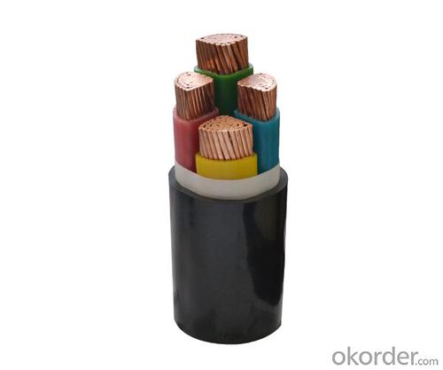
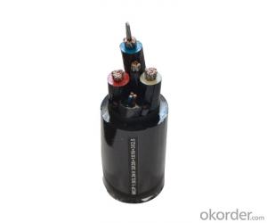
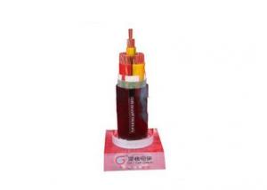
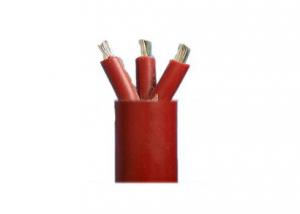
PVC insulated and sheathed control cable is suitable for connections of electric equipment
- Ref Price:
-

- Loading Port:
- Tianjin
- Payment Terms:
- TT or LC
- Min Order Qty:
- 100 m
- Supply Capability:
- 100000 m/month
OKorder Service Pledge
OKorder Financial Service
You Might Also Like
Brief introdution
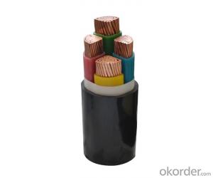
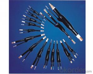
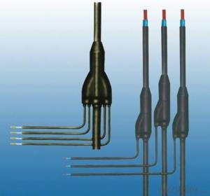
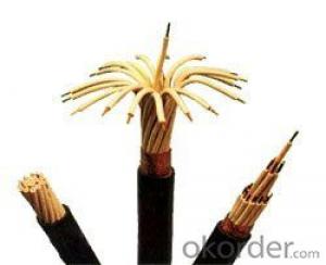
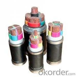
PVC insulated and sheathed control cable is suitable for connections of electric equipment in controlling monitoring loop and circuit protecting at rated voltage up to and including 450/750v (A.C.) The product has excellent characteristics not only in electric and mechanical purposes but also in chemical corrosion resistance. Heat-aging, environmental stress and flame-retardant.The product is simple in structure and convenient to use and could be laid with no restriction of different levels.
Our product of PVC insulated and sheathed control cable can be manufactured according to the standard GB 933088 which is drawn up by reference to IEC227 and IEC 502 as well as the standards of Germany, America, Japan and so on, For control cable we can also design and manufacture special control cable according to other standards or requirement of customers.
The properties of flame-retardant control cable are in accordance with the apceifications in IEC332-3, Type ZR-KVV of our control cable has been manufactured with various sizes. Welcome to choose our control cable.
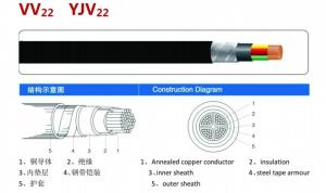
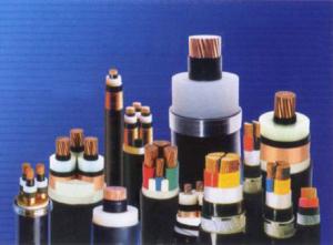
Features:
Type | Designation | Main Applications |
KVV | Copper core PVC insulated and sheathed control cable | For laying indoor, tunnels, ducts, conduit etc.permanent place. |
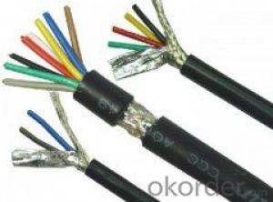
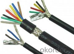
KVVP | Copper core PVC insulated and sheathed copper wire shielded control cable | For laying indoor, ducts. Conduit etc. permannet place where shield is required. |
KVVP2 | Copper core PVC insulated and sheathed copper tape shielded control cable | Ditto |
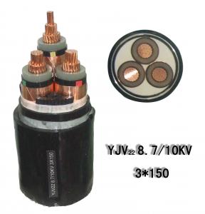
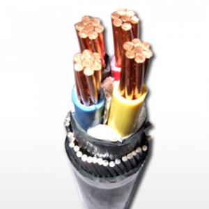
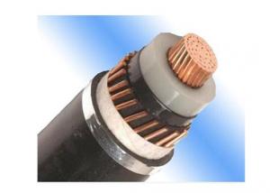
KVV22 | Copper core PVC insulated and sheathed steel tape armoured control cable | For laying indoor, tunnels, ducts, conduit and direct burial etc.Pemanent place, able to bear greater mechanical force. |
KVV32 | Copper core PVC insulated and sheathed fine steel wire armoured control cable | For laying indoor, tunnels, ducts, conduit and shaft etc.permanent place, able to bear greater pulling force. |
KVVR | Copper core PVC insulated and sheathed flexible control cable. | For laying indoor and flexible required etc. place easy to move. |
KVVRP | Copper core PVC insulated and sheathed copper wire braiding shielded flexible control cable | For laying indoor, and flexible and shield required etc. place easy to move. |
ZR-KVV | Copper core PVC insulated and sheathed flame-retardant control cable. | For being applied on heat engine and heat controling appliance. |
Specification:
No. of core & Nominal cross section mm2 | Conductor Construction No./dia. mm | Norminal insulation thickness mm | Nominal sheath thickness mm | Overall Dia. mm | Weight kg/km | Resistance of conductor at 20℃ Max. Ω/km | Insulation resistance at 70℃ Min. MΩ.km | Test voltage V |
3 x 0.75A | 1/0.97 | 0.6 | 1.2 | 8.4 | 68 | 24.5 | 0.012 | 3000 |
10 x 0.75A | 1/0.97 | 0.6 | 1.2 | 12.5 | 174 | 24.5 | 0.012 | 3000 |
24 x 0.75A | 1/0.97 | 0.6 | 1.5 | 18.0 | 376 | 24.5 | 0.012 | 3000 |
48 x 0.75A | 1/0.97 | 0.6 | 1.7 | 23.0 | 689 | 24.5 | 0.012 | 3000 |
Table 1.2
No. of core & Nominal cross section mm2 | Conductor Construction No./dia. mm | Norminal insulation thickness mm | Nominal sheath thickness mm | Overall Dia. mm | Weight kg/km | Resistance of conductor at 20℃ Max. Ω/km | Insulation resistance at 70℃ Min. MΩ.km | Test voltage V |
3 x 0.75B | 7/0.37 | 0.6 | 1.2 | 8.8 | 72 | 24.5 | 0.014 | 3000 |
10 x 0.75B | 7/0.37 | 0.6 | 1.2 | 13.5 | 183 | 24.5 | 0.014 | 3000 |
24 x 0.75B | 7/0.37 | 0.6 | 1.5 | 19.0 | 396 | 24.5 | 0.014 | 3000 |
48 x 0.75B | 7/0.37 | 0.6 | 1.7 | 25.0 | 726 | 24.5 | 0.014 | 3000 |
Table1.3
No. of core & Nominal cross section mm2 | Conductor Construction No./dia. mm | Norminal insulation thickness mm | Nominal sheath thickness mm | Overall Dia. mm | Weight kg/km | Resistance of conductor at 20℃ Max. Ω/km | Insulation resistance at 70℃ Min. MΩ.km | Test voltage V |
3 x 1A | 1/1.13 | 0.6 | 1.2 | 8.8 | 79 | 18.1 | 0.011 | 3000 |
10 x 1A | 1/1.13 | 0.6 | 1.2 | 14.0 | 223 | 18.1 | 0.011 | 3000 |
24 x 1A | 1/1.13 | 0.6 | 1.5 | 19.0 | 451 | 18.1 | 0.011 | 3000 |
48 x 1A | 1/1.13 | 0.6 | 1.7 | 24.5 | 835 | 18.1 | 0.011 | 3000 |
Table 1.4
No. of core & Nominal cross section mm2 | Conductor Construction No./dia. mm | Norminal insulation thickness mm | Nominal sheath thickness mm | Overall Dia. mm | Weight kg/km | Resistance of conductor at 20℃ Max. Ω/km | Insulation resistance at 70℃ Min. MΩ.km | Test voltage V |
3 x 1B | 7/0.43 | 0.6 | 1.2 | 9.2 | 83 | 18.1 | 0.011 | 3000 |
10 x 1B | 7/0.43 | 0.6 | 1.2 | 15.0 | 235 | 18.1 | 0.013 | 3000 |
24 x 1B | 7/0.43 | 0.6 | 1.5 | 20.5 | 474 | 18.1 | 0.013 | 3000 |
48 x 1B | 7/0.43 | 0.6 | 1.7 | 26.5 | 877 | 18.1 | 0.013 | 3000 |


- Q: So I've had my laptop for about a year and a half now and I've gone through 4 power cables, 3 non-factory. What happens with each one is, I plug it in, the blue light surrounding the hole turns on, the end of the power cable that plugs into my laptop gets super hot and either melts the power cable, or when I plug the cable in, the light won't come on unless I have it in just right. This usually starts to happen between one and three months after I get a new cable. It's starting to go through them faster now, any ideas?
- you have a power short in the computer that's why it is getting to hot and melting the cables, get it seen to immediately
- Q: or do I need to buy one?
- Yes it's a standard 3 prong pc plug.
- Q: It's provided to me by my ISP which is Cox. If I were to unplug the power cord what would happen, would my phone no longer work without another technicians appointment. I know that the motorola cable modem with no phone service you can power cycle that one.
- With my Cable company it's the first thing you do (or the first thing tech support tells you to do) when there is any problem. It is set up to restart after power failures and brownouts, so I would say go ahead. If the phone doesn't work after you power cycle, Power cycle again and see if that time works.
- Q: Ok A few months ago i bought parts for a brand new pc and recently got the video card and well the power supply PCI-e cable is a 6 pin and the motherboard requires a 4 pin. A friend said there are adapters but i've only seen one and it was not very good rating wise. So I'm looking to find out if there are adapters or if i need to get another power supple.
- See how that one is a 4pin connector and has 2 extra pins that are snapped on the side?
- Q: I mean like the power connector cables. All power supplys have the same cables to supply power from the PSU to components right?
- no all smps don't have same cable you have to purchase same smps as you using right now or according to your motherboard
- Q: What are the causes of the power cable fire accident? How to prevent
- Notebook does not have the opportunity to DIY. The reasons are as follows: Notebook motherboard non-versatile motherboard, the shape of the motherboard, positioning holes, screw holes are not uniform standards, each manufacturer's motherboards are their own engineers and then open factory production model. Notebook shell corresponding to the interface location, type and screw hole location is with a specific motherboard supporting.
- Q: The other day I found an imac g5 17computer in my alley. It probably doesn't work but I was just curious about what cables/accessories I need for it. All that was out there was the actual monitor/desktop. There were no cables with it. (By the way if you can't tell I am not experienced with computers)Thanks any info is appreciated!
- Power cable, USB keyboard, USB mouse. That's it. Find a power cable (any old computer power cable will work) and see if it even powers on and does anything first. Crack it open. Set it on its face, then undo the three screws across the bottom. They do NOT come out. They only loosen up until you can't turn them anymore. The back pops off. Look for any swollen or leaking capacitors. If you find any, then it's junk. If you don't, then see if there's any RAM in it. If not, toss some PC3200 DDR RAM in there and see if you get anything.
- Q: if we provide power through power cable will there be need of extra capacitor near load?
- Yes, if you are talking about a bypass capacitor. Electronics always requires a bypass capacitor near the circuit/IC. Having one at the end of a cable means the cable inductance is in series, and the impedance seen by the IC power supply leads is inductive and high instead of the needed low impedance that a local bypass cap provides.
- Q: It's a 250GB Western Digital Caviar drive, sold with an iMac back in early 2007... I want to see if I can recover some files from it, but I have no idea where to start.
- Get an external adapter kit. Tiger direct sells them.
- Q: Is a graphics card power cable needed because not all graphics cards come with one? And if it isn't needed, what is the benefit?
- not all graphic cards need them. But lately the graphic cards are using up quite a bit of power, especially the high-end ones. So if the graphic card has a pci-e power connector. Chances are it will need it. Otherwise your computer might show graphics are there will be error when trying to play games or other graphic intense applications. The same thing is happening to graphic cards, that happen to processor a few years ago. Not that long ago processors could just be powered by the energy coming from the bus line on the motherboard, but that is not true anymore and now we use 4-pin or the new 8 pin axillary power for the processor.
Send your message to us
PVC insulated and sheathed control cable is suitable for connections of electric equipment
- Ref Price:
-
- Loading Port:
- Tianjin
- Payment Terms:
- TT or LC
- Min Order Qty:
- 100 m
- Supply Capability:
- 100000 m/month
OKorder Service Pledge
OKorder Financial Service
Similar products
Hot products
Hot Searches
Related keywords

