
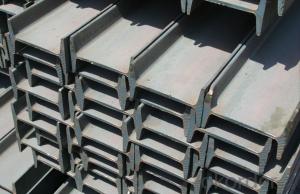
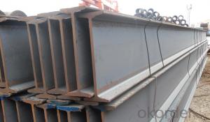
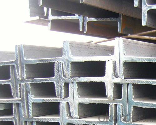


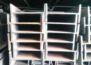
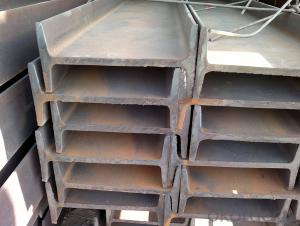
High quality IPEAA
- Ref Price:
-

- Loading Port:
- China Main Port
- Payment Terms:
- TT OR LC
- Min Order Qty:
- -
- Supply Capability:
- -
OKorder Service Pledge
OKorder Financial Service
You Might Also Like
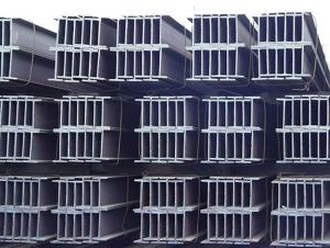
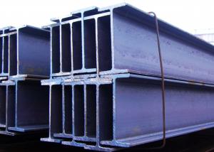
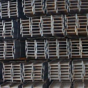
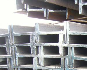
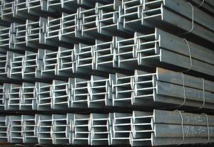
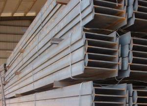
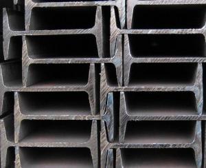
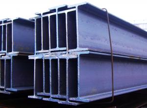
Product Description:
IPEAA Beam Details:
| Minimum Order Quantity: | 10MT | Unit: | m.t. | Loading Port: | Tianjin Port, China |
| Supply Ability: | 10000MT | Payment Terms: | TT or LC | | |
Product Description:
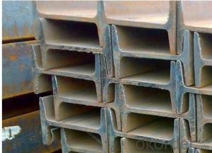
Specifications of IPEAA Beam
1. Invoicing on theoretical weight or actual weight as customer request
2. Standard: EN10025, GB Standard, ASTM
3. Grade: Q235B, Q345B, SS400, ASTM A36, S235JR, S275JR
4. Length: 5.8M, 6M, 9M, 12M as following table
5. Sizes: 80mm-270mm
Dimensions(mm) | |||||
| h | b | s | t | Mass Kg/m |
IPEAA80 | 80 | 46 | 3.80 | 5.20 | 6.00 |
IPEAA100 | 100 | 55 | 4.10 | 5.70 | 8.10 |
IPEAA120 | 120 | 64 | 4.80 | 6.30 | 10.40 |
IPEAA140 | 140 | 73 | 4.70 | 6.90 | 12.90 |
IPEAA160 | 160 | 82 | 5.00 | 7.40 | 15.80 |
IPEAA180 | 180 | 91 | 5.30 | 8.00 | 18.80 |
IPEAA200 | 200 | 100 | 5.60 | 8.50 | 22.40 |
IPEAA220 | 220 | 110 | 5.90 | 9.20 | 26.20 |
IPEAA240 | 240 | 120 | 6.20 | 9.80 | 30.70 |
IPEAA270 | 270 | 135 | 6.60 | 10.20 | 36.10 |
Appications of IPEAA Beam
1. Supporting members, most commonly in the house raising industry to strengthen timber bears under houses. Transmission line towers, etc
2. Prefabricated structure
3. Medium scale bridges
4. It is widely used in various building structures and engineering structures such as roof beams, bridges, transmission towers, hoisting machinery and transport machinery, ships, industrial furnaces, reaction tower, container frame and warehouse etc.
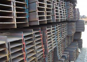
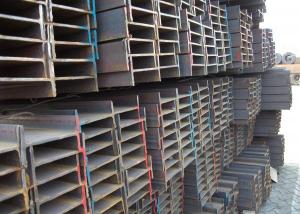
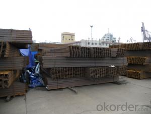
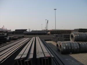
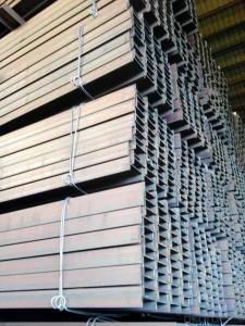
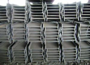
Package & Delivery of IPEAA Beam
1. Packing: it is nude packed in bundles by steel wire rod
2. Bundle weight: not more than 3.5MT for bulk vessel; less than 3 MT for container load
3. Marks: Color marking: There will be color marking on both end of the bundle for the cargo delivered by bulk vessel. That makes it easily to distinguish at the destination port.
4. Tag mark: there will be tag mark tied up on the bundles. The information usually including supplier logo and name, product name, made in China, shipping marks and other information request by the customer.
If loading by container the marking is not needed, but we will prepare it as customer request.
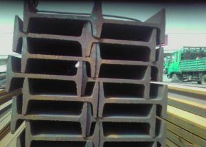
5. Transportation: the goods are delivered by truck from mill to loading port, the maximum quantity can be loaded is around 40MTs by each truck. If the order quantity cannot reach the full truck loaded, the transportation cost per ton will be little higher than full load.
6. Delivery of IPE Beam: 30 days after getting L/C Original at sight or T/T in advance
Production flow of IPEAA Beam
Material prepare (billet) —heat up—rough rolling—precision rolling—cooling—packing—storage and transportation
- Q: What are the different types of load tests conducted on Steel I-Beams?
- There are several types of load tests conducted on steel I-beams to evaluate their structural integrity and performance. These tests can provide critical information about the beam's strength, stiffness, and resistance to various types of loads. The different types of load tests commonly conducted on steel I-beams include: 1. Ultimate Strength Test: This test aims to determine the maximum load a steel I-beam can withstand before failure or collapse. It helps in assessing the beam's ultimate strength and ensures that it can safely support the intended loads. 2. Yield Strength Test: This test determines the load at which the steel I-beam begins to deform plastically or permanently. It helps in understanding the beam's yield strength, which is crucial for designing structures and ensuring their safety. 3. Deflection Test: This test measures the amount of deflection or bending that occurs in the steel I-beam under a specific load. It allows engineers to evaluate the beam's stiffness and its ability to resist excessive deflection, which is essential for maintaining the structural integrity of a building. 4. Fatigue Test: This test assesses the endurance limit of a steel I-beam by subjecting it to repeated loading cycles. It helps determine the beam's resistance to fatigue failure, which is crucial in applications where cyclic loads or vibrations are expected. 5. Impact Test: This test evaluates the steel I-beam's ability to absorb sudden impact loads without fracturing or excessively deforming. It simulates real-life scenarios where the beam may encounter unexpected loads, such as accidental impacts or dynamic forces. 6. Buckling Test: This test examines the steel I-beam's resistance to buckling or sudden lateral instability under compressive loads. It helps in determining the beam's critical buckling load and ensuring its stability in vertical or horizontal applications. These different types of load tests provide valuable insights into the performance characteristics of steel I-beams and assist engineers in designing safe and efficient structures. By conducting these tests, the structural integrity and load-bearing capacity of the beams can be accurately assessed, ensuring the overall safety and reliability of the constructed infrastructure.
- Q: Are Steel I-Beams fire resistant?
- Yes, steel I-beams are generally considered to be fire resistant due to their high melting point and ability to retain their structural integrity even under extreme heat.
- Q: What does "I-beam 125A" mean?
- The same height of the I-beam, if there are several different leg width and waist thickness, need to add a, B, C on the right side of the model to distinguish, such as 32a, 32B, 32c and so on.
- Q: How do steel I-beams compare to timber beams in terms of strength?
- Steel I-beams are significantly stronger than timber beams. Steel has a much higher tensile and compressive strength compared to timber, making it more suitable for carrying heavy loads and resisting bending or sagging. Additionally, steel is more resistant to fire, rot, and pests, providing greater durability and longevity.
- Q: What are the standard dimensions for steel I-beams?
- The specific design and application of steel I-beams determine their standard dimensions, which can vary. However, there are commonly used sizes in construction and engineering projects. Steel I-beams typically have the following dimensions: - Flange Width: The horizontal dimension of the I-beam's top and bottom sections usually ranges from 2 to 14 inches. - Web Thickness: The vertical dimension of the I-beam's center section, connecting the top and bottom flanges, typically ranges from 0.18 to 1.07 inches. - Flange Thickness: The thickness of the I-beam's top and bottom sections ranges from 0.36 to 1.22 inches. These dimensions can be adjusted based on load-bearing requirements and the specific structural application of the steel I-beam. It is essential to consult relevant engineering and construction standards, as well as structural engineers, to determine the appropriate sizing and design considerations for any specific project.
- Q: How do steel I-beams perform in terms of impact insulation?
- Steel I-beams are not typically used for impact insulation purposes. They are primarily used for structural support in construction projects. However, due to their rigid and dense nature, they may provide some level of impact resistance. In the event of an impact, steel I-beams are designed to withstand the force and distribute it along their length, minimizing the impact's effect on the surrounding structure. Nonetheless, their ability to absorb or dampen impact energy is limited compared to materials specifically designed for impact insulation, such as foam or rubber. If impact insulation is a critical requirement, it is advisable to explore other materials or methods specifically designed for this purpose.
- Q: Can steel I-beams be used for cantilever structures?
- Yes, steel I-beams can be used for cantilever structures. Cantilever structures are designed to have one end anchored or supported while the other end extends outwards, creating an overhang. Steel I-beams are often used in cantilever structures due to their strength, rigidity, and ability to span long distances. The I-shape provides excellent load-bearing capabilities, allowing the beam to support the weight and distribute the load evenly. Additionally, steel I-beams can be easily fabricated and customized to meet specific project requirements, making them a popular choice for cantilever structures in various applications such as bridges, balconies, and building façades.
- Q: What are the considerations for fire rating steel I-beams?
- There are several factors to consider when evaluating the fire rating of steel I-beams. First and foremost, the fire resistance of the I-beams is crucial. This is determined by the type and thickness of the fireproofing material applied to the beams. Common fireproofing materials for steel I-beams include intumescent coatings, which expand when exposed to heat and create an insulating layer to protect the steel from fire. It is important to ensure that the fire resistance rating of the I-beams meets the requirements set by local building codes and regulations. Another factor to consider is the load-bearing capacity of the I-beams during a fire. Although steel I-beams are designed to carry heavy loads, the high temperatures in a fire can weaken their structural integrity. Therefore, it is essential to ensure that the I-beams can withstand both the weight loads and the potential impact of a fire without compromising their stability. The fire protection system in the building should also be taken into account. This includes the presence of fire alarms, sprinklers, and other fire suppression systems that can help control or extinguish a fire. These systems provide additional protection to the steel I-beams and prevent the fire from spreading further. Furthermore, the fire rating of the steel I-beams should be compatible with the fire resistance of other building components, such as walls, floors, and ceilings. If the I-beams are supporting these components, they should have a fire rating that matches or exceeds the fire rating of the surrounding materials. Lastly, the intended use and occupancy of the building should be considered. Different occupancy types have different fire safety requirements, which may influence the necessary fire rating for the steel I-beams. For instance, buildings with high occupancy loads or those housing flammable materials may require higher fire resistance ratings for the I-beams. In conclusion, when evaluating the fire rating of steel I-beams, it is important to carefully assess factors such as fire resistance, load-bearing capacity, fire protection systems, building construction, and occupancy type. This ensures the safety and compliance of the structure.
- Q: How do steel I-beams perform in high-wind stadium applications?
- Steel I-beams perform well in high-wind stadium applications due to their strength and stiffness. The structural integrity and load-bearing capacity of I-beams make them capable of withstanding the wind forces exerted on the stadium. Additionally, the design and placement of these beams are carefully engineered to ensure optimal performance and safety, making them a reliable choice for such applications.
- Q: What are the tensile, shear, Xu Yun, and Xu Yun deflections of 20a I-beam?
- According to the probability method of allowable value:For materials with Q235B i-beam. The tension and compression allowance is 157MPa; the shear zone is 90-100MPa; the allowable deflection is 1/500 of the span.
Send your message to us
High quality IPEAA
- Ref Price:
-
- Loading Port:
- China Main Port
- Payment Terms:
- TT OR LC
- Min Order Qty:
- -
- Supply Capability:
- -
OKorder Service Pledge
OKorder Financial Service
Similar products
Hot products

Hot Searches
Related keywords

