


Galvanized Iron wire/ Binding wire or building wire Corrosion- resistant
- Ref Price:
-

- Loading Port:
- Tianjin
- Payment Terms:
- TT OR LC
- Min Order Qty:
- 8000 kg
- Supply Capability:
- 3000000 kg/month
OKorder Service Pledge
OKorder Financial Service
You Might Also Like


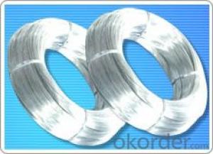
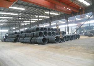
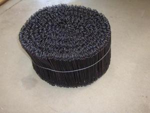
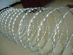
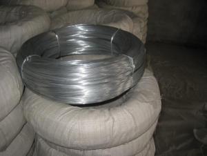
1.Structure of Galvanized Iron Wire Description:
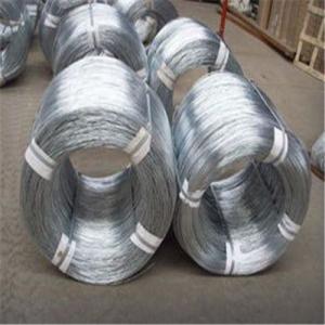
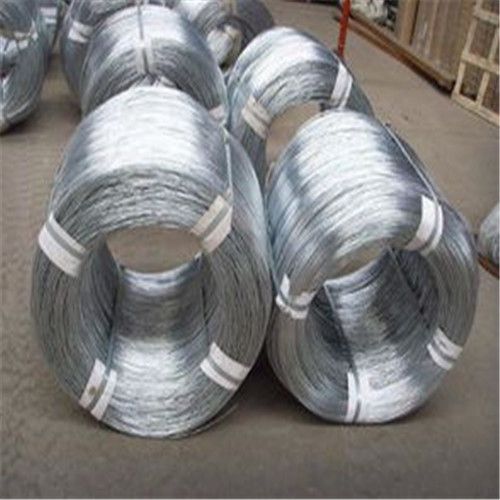
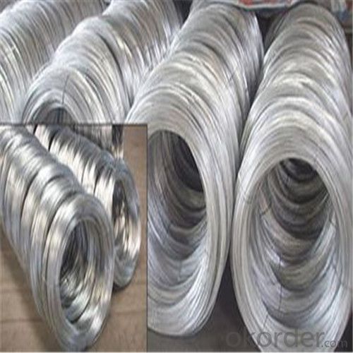
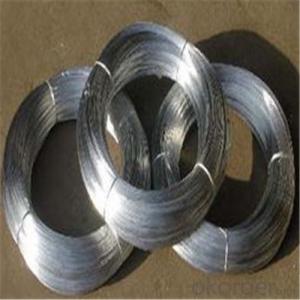
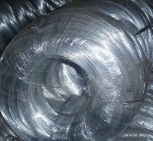
Galvanized Iron Wire has the characteristics of thick zinc coating, good corrosion resistance, firm zinc coating, etc.
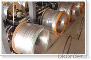
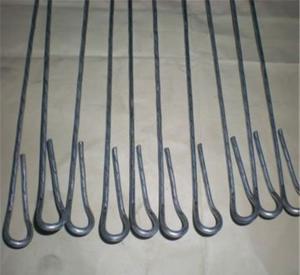
Galvanized Iron Wire mainly used in construction, express way fencing, binding of flowers and wire mesh weaving. Galvanized iron wire according to manufacturing technique, it includes hot-dipped galvanized iron wire and electro galvanized iron wire. Mainly telecommunication equipment and materials, medical equipment and device, weaving of wire mesh, steel rope, and filtration mesh, high-pressure pipe, construction, arts and crafts, etc
2.Main Features of Galvanized Iron Wire:
• Use widely
• Corrosion- resistant
• Durable
• Practical use
• Beauty Surface
• Versatile
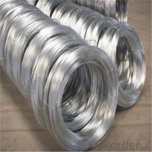
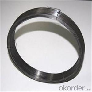
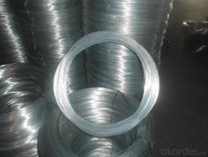
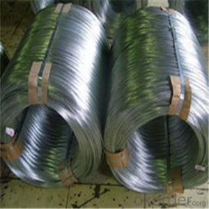
3. Galvanized Iron Wire Images


4. Galvanized Iron Wire Specification

5.FAQ
We have organized several common questions for our clients,may help you sincerely:
①How about your company?
One of the most biggest manufacturer & supplier of wires and wire mesh,is a large-scale professional Galvanized Iron Wire factory in China. Annually more than 10000 tons wires and wire mesh are exported to markets all over the world. Different kinds of wires and mesh are available according to customer’s requirements.
②What is the Technical Information of the Galvanized Iron Wire?
1).Material: super carbon steel
2).Processing by drawing, hot-dip zinc-plating
3).Standard wire gauge from 8# to 24#
4).Thick zinc-coating layer
5).Super in corrosion resistance
6).Firm coating layer
7).Custom size available
③How long can we receive the product after purchase?
In the purchase of Galvanized Iron Wire within three working days, We will arrange the factory delivery as soon as possible. The pacific time of receiving is related to the state and position of customers. Commonly 15 to 20 working days can be served.
- Q: Three parallel wires are each carrying a 4A current. ; wire A) is 6 mm from wire B) which is 3mm from wire C); The current in wires B and C are out of the paper, while A is into the paper. What is the magnitude and direction of the magnetic field halfway between wires A and B?I have tried using Biot-Savart Law but keep getting it wrong can someone please help? I also have an equation for two parallel wires but how do I relate it to two?
- You can use the Biot-Savart Law, but it is confusing and kind of a waste of your time and space. For straight wires, someone ALREADY worked out the Biot-Savart Law. See the following link for the result: hyperphysics.phy-astr.gsu.edu/Hba... The formula of interest for us is B = mu0*I/(2*Pi*r) where mu0 is magnetic permeability of free space, I is current, and r is distance from the wire carrying the current. B is the magnetic field due to that PARTICULAR wire. To deal with three wires, use a superposition principle and stack magnetic fields on top of each other. Do be aware of direction: remember the right hand rule. RH rule for magnetic fields in vicinity of wires: point thumb in direction of current, curl fingers to show the magnetic field circulation direction. Use this sign convention: + B is up along page, -B is down along page For Wire A: point of interest is r = d_ab/2 or 0.003 m to the right of wire A Point thumb in to the paper and the finger curl indicates that B_A is downward B_A = -mu0*I_A/(pi*d_ab) For Wire B: point of interest is r = d_ab/2 or 0.003 m to the left of wire B Point thumb out of the paper and the finger curl indicates that B_B is downward B_B = -mu0*I_B/(pi*d_ab) For wire C: point of interest is r = d_ab/2 + d_bc or 0.006 m to the left of wire C Point thumb out of the paper and the finger curl indicates that B_C is downward B_C = -mu0*I_C/(2*pi*(d_ab/2 + d_bc)) Add up: Bnet = B_A + B_B + B_C Bnet = -mu0*I_A/(pi*d_ab) - mu0*I_B/(pi*d_ab) - mu0*I_C/(2*pi*(d_ab/2 + d_bc)) Simplify: Bnet = -mu0/pi*(I_A/d_ab + I_B/d_ab + I_C/(d_ab + 2*d_bc)) data: mu0:=4*Pi*10^(-7) Tesla-m/A; I_A:=4 A; I_B:=4 A; I_C:=4 A; d_ab:=0.006 m;d_bc:=0.003 m; Result: Bnet = -6.667 milliTeslas negative sign indicates downward direction.
- Q: how do I replace this, the wire is built into the speaker and runs into the unit.
- Easy to replace. Just get a new dog. Small breed if it's a tweeter. Beagle sized for mid-range. And of course Lab or larger for that all important Woof-Woofer.
- Q: I bought a single pole dimmer switch to install in my dining room and when I took the old switch out nothing looked right. There are two wires which were joined together by another single wire which was attached to the top screw. There was another single wire (I believe the ground wire) attached to the bottom screw. I disconnected the first two wires and attached them separately to the black wires on the dimmer and attached the ground wires together. It didn't work. I've tired several different times with no luck. I put the wires back the way they were and attached them to the old switch and they no longer work ether. Help! How can I fix this problem? The old wires appear to be a very thick copper covered in black plastic and cloth.....
- The 'answerer' Justin K thinks you have knob and tube wiring. A lot of early electrical installations were done in the old days with out a ground, many types of early 'romex' did not include a ground. You may or may not have 'knob and tube' wiring - but it really dose not matter. The two wires which were joined together and had a third wire attached are the hot wires. The other wire (lower screw terminal) is the 'load' wire - it goes out to your light fixture. The reason the those 2 wires were attached together is that one of them is hot, and the other wire is a 'feed' to supply power to your next switch or receptacle. I am an electrical contractor, this is how I would fix the problem - I'm not suggesting that you do it though. #1 turn the breaker/fuse back on. #2 use a voltage tester to determine which wire is now hot. #3 touch the hot wire to the other wires 1 at a time. The hot wire when it is touching the 'load' wire will turn on the lighting fixture. Mark the 'load' wire with some black electrical tape. #4 turn the power back off #5 attach the marked 'load' wire to one of the switch terminals. #6 take the other 2 wires (incoming power, and the out going power) and join them together with a third wire ---LIKE IT WAS ORIGINALLY. Place that third onto the other terminal of the switch. it dose not mater which terminals you use - it will work just fine.
- Q: Okay so I just finished replacing a stolen car radio, but I think I messed up the wiring... When I turn off the car the radio doesn't seem to save the presets I had... it resets the whole stereo... I think it has something to do with the wiring I did... When I installed the radio there were two 12+ volt wires... One said 12+ volt constant and was yellow, and the other said 12+ volt switch and was pink... Problem was when I wired only the yellow one the car stereo wouldn't work, so I tried the pink one and that didn't work.. SO thinking I was clever I wired both to the 12+ volt and VOILA the radio turned on... Problem is I don't think that's how I was supposed to wire it... I have a '97 Honda accord Ex and I don't know if that's what I was supposed to do... :#92;
- A car stero needs 3 main wires Constant Power (Normally Yellow) for memory like radio presets Switched Power (Normally Red) Switched by the cars ignition so your radio turns on/off with your keys You can wire these two together as long as its a constant feed, youll just have to turn it off yourself... but then it will work when the ignition is off as well that way and Earth (Normally black) The rest of the wires if you pay attention you can pair them up to form the front speakers and rear speakers, it looks to me like... this is going to take sometime to get my head around ill edit it ounce ive worked it out... Either way youv got your red and black there thats positive and negative, it will turn on with those. How many speakers in the car, and are they orginal, I asume all wires have an open end? the four black and white ones sound like someones added them, and put non orginal speakers in.
- Q: i am trying to wire my aftermarket tailight, and it did not come with the plug in adapter as the original. The three wires coming out of it are glued together in a bell type casing. Pls Help!!
- The wire that is hooked to the tail light BODY is the ground wire.One wire goes to the brake light switch and the other one goes to the tail light hot wire.With a test light you can determine where each one is to be hooked to.
- Q: I made a kill switch for my car. All I need to do now is cut the wire that goes into my engine control module and join it with the switch I made. Would it be fine if I just use wire nuts or some sort of tape to join the wires instead of soldering? The instructions say quot;Step 6: Attach the killswitch wires one to each side of the wire you just cut. Step 7: Tape up all new connection.quot;It says to tape the new connections, but should I use exactly?
- Twisted wires can separate with the daily rattle and bumps of a car. I would crimp or solder it along with a shrink tube to secure it.
- Q: Like I hear people say If you have good Wires you will have good bass. What is good wiring. What is the best wires I can get. Help me I'm new at this. Post some links or Something. 5 stars for best. Thanks!
- that sounds like a quote you'd only hear a sales person say. Power wire, ground wire, speaker wire -- just needs to be adequate gauge. Some of the lower price brands are less than honest. Selling wire that's claimed to be 4 gauge, but closer to 6. The higher price stuff generally just uses smaller individual strands making the wire very flexible. That could be helpful, or make no difference at all. RCA's -- the myths abound. Monster cable (and several others) would like you to think you need to spend $100+ on signal cables to get high quality sound. Not true at all. The $5 cables at walmart will transfer signal as well as the $50 ones. The biggest difference is durability. The higher price cables will have higher quality ends and SHOULD last longer especially when they're plugged in and unplugged often.
- Q: i am going to be installing a flood light outside, i am running the wire on the outside of the house. i have down some small electrical work light outlets and switches but not sure on running wire. i was looking at lowes at outdoor wire and there are different size gauges. just wondering what size or gauge is best to use for an outdoor flood light?
- Previous answer was partially correct. There are building codes depending on your local government. Some outside wires have to be in conduit, some have to enter and exit the ground in conduit, others do not require it. However, the wire size is associated with the circuit breaker that you are going to attach it to and the length or distance away from the circuit board it is going to be. Don't try to save money and buy indoor wire however, stick to the heavier outdoor coated wire. It is best to buy a higher Gage and not use it all then to buy a Gage that is too small.
- Q: what are the differences between wired and wireless microphones? and what are the Pros and Cons of having a wired mic, pros and cons of a wireless?Thanks......
- Wired microphones have a wire to connect it. Wireless ones don't. Pros and cons? Do you want wires?
- Q: What are some of the basic advantages of twisted pair wiring?
- Less interference.
Send your message to us
Galvanized Iron wire/ Binding wire or building wire Corrosion- resistant
- Ref Price:
-
- Loading Port:
- Tianjin
- Payment Terms:
- TT OR LC
- Min Order Qty:
- 8000 kg
- Supply Capability:
- 3000000 kg/month
OKorder Service Pledge
OKorder Financial Service
Similar products

Hot products

Hot Searches
Related keywords

