
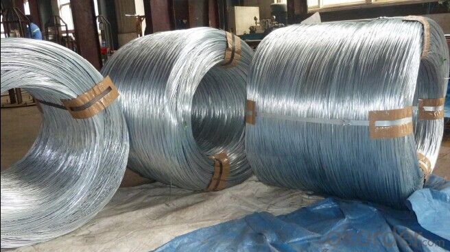
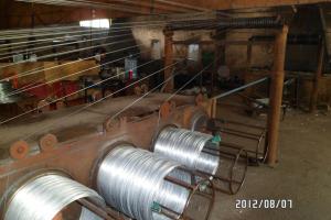
Electro Galvanised Steel Wires
- Ref Price:
-

- Loading Port:
- China Main Port
- Payment Terms:
- TT OR LC
- Min Order Qty:
- -
- Supply Capability:
- -
OKorder Service Pledge
OKorder Financial Service
You Might Also Like


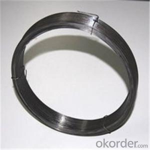


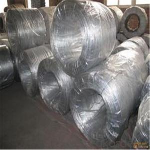
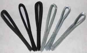
Galvanized Wire/Galvanized Steel Wire/ Gavanized Iron Wire
Diatmeters:0.15mm-6mm
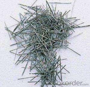
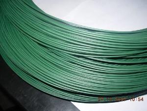
Application | Weaving, braiding, fencing, cable armoring, knitting, tie wire, for redrawn, for binding or forming etc. |
Material | low carbon steel wire |
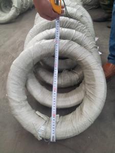
Diameter | 0.15mm~6.00mm |
Tensile strength | 350-500MPA, or higher |
Zinc coating | Min 12g/m2, min 25g/m2, min 200g/m2,min 300g/m2,610g/m2 |
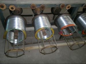
Surface treatment | Hot dipped or electro galvanized |
Packing | On spools In small coils of 25-50kg/coil, 10kg/coil In rosette coil of 100-800kg/coil |
Standard | ASTM 641, EN10257-1& EN10244-2 |
All can be produced according to customers’ requirements.
- Q: Where would I get a 2001 wiring diagram for a Silverado chevy truck? I want to re-install the factory stereo that was taken out when I first got it? I have no idea what wire goes where. Thanks a lot.
- Speaker Wiring Diagram
- Q: Need wiring diagram for ford F250 2004 disel
- Radio 12v lt. green/purple + radio harness Radio Ground black and black/lt. green - radio harness Radio Ignition pink/black or lt. green/yellow + radio harness Radio Illumination lt. blue/red (dimmer) + radio harness Factory Amp Turn-on dk. green/purple + radio harness Notes: This is the subwoofer amplifier turn on lead. The subwoofer and amp are in the driver side rear corner of the cabin. The subwoofer speaker wires are brown/orange (+), and red/black (-) at the radio harness. Power Antenna N/A LF Speaker +/- orange/lt. grn - lt. blue/wht +,- radio harness RF Speaker +/- white/lt. grn - dk. green/org +,- radio harness LR Speaker +/- gray/lt. blue - tan/yellow +,- radio harness RR Speaker +/- orange/red - brown/pink +,- radio harness Immobilizer Bypass Module: Required: Yes Type: SecuriLock Part #: 555U
- Q: coil wiring diagram
- The two small wires are positive and negative. Most are color coded and if it's a OEM part, the negative will be the same color as the group of smaller wires connected to the negative battery cable. Each manufacturer uses different color codes and for instance, Kawasaki uses black with yellow stripe. The other wire will go to the positive side. If the coil doesn't have wire coming out if it, it may have a + or - sign by the terminals. In actuality, it doesn't really matter which way you hook it up because a coil doesn't really care which way the electricity travels. It's the collapsing magnetic field that creates the spark and not the direction or movement of electricity.
- Q: When I am wiring my sub to my amp, what gauge of wire should I use? The sub is 750 rms and the amp is 700 rms. And how do I wire a 2 ohm sub DVC to a 2 ohm stable amp?
- the present passing for the duration of the wires will reason the wires to warmth up if no longer sufficient guage. think of of the hundreds of thousands of little electrons pushing and shoving returned and forth, all this action motives friction on a molecular point and of direction all of us understand friction equals warmth. In a bigger guage twine there is extra area for the comparable form of electons. it truly is truly that straightforward. Use as heavy a guage speaker twine which you would be able to. you will have no sign loss and little warmth.
- Q: what wires are my speaker wires going to and coming from the factory amp and how do i hook them up please help i drive a 96' ford exploder
- aamp of america has a psa interface part# BHA 5511. It works great The other way is to rewire from the psa to the radio. The psa is over the r rr wheel well (a real pain in the butt to get to)
- Q: i got a fi bl 15dual 2 subwoofer. im wiring it down to 1 ohm.now for the problem. lets say im wiring the positive terminals together. am i suppose to wire it all with positive wire or can i also use negative copper wire? i used two positive wires and one negative wire to hook up the three positive terminals. is this bad? do i need to make all of them positive silver wires?
- Wire is just wire. It alone does not know positive from negative. However, some great problems could lie below the surface. It really depends on what is on the other end of the wire. There may be some problems associated with not following a good wiring practice such as: Creating a short circuit and blowing the amp Putting one of the two speakers out of polarity with the other resulting in lower or no acoustical output. The best practice is to ALWAYS relate the positive or PLUS terminal with the wire with the same designation with the speaker terminal. That way, if you have to do any trouble shooting, you can trace is back and know without a doubt what is connected to what.
- Q: Given following setup of three wires in the plane of the page with I1 = 1.3 A (to the right), I2 = 3.4 A (to the right), I3 = 4.5 A(to the left) and each wire is separated by 3 m.I'm completely lost, I need to..1. What is the direction of the magnetic field at wire 3 due to wires 1 and 2?2. What is the direction of the force on wire 3 due to wires 1 and 2?Any help would really be appreciated! Thanks!
- I assume that those wires are sitting parallel 3 m apart from one another. 1. The magnetic field around a wire forms concentric circles around the wire. Wire 1 and Wire 3 are parallel so when you draw a concentric field line around Wire 1 with radius 6 m, you get a magnetic field line passing Wire 3 at a right angle. And a concentric field line around Wire 2 with radius 3 m passes Wire 3 at a right angle. Both magnetic fields have the same direction because the current in both wires flows in the same direction (to the right). Using the right-hand rule, you can find that the magnetic field at wire 3 due to Wire 1 and Wire 2 goes into the page. Ans: Into the page 2. The force on a wire can be calculated in the following manner: I X B * L. Here I is the current on Wire 3, B is the magnetic field due to Wire 1 and Wire 2, L is the length of Wire 3, and X is the cross product operator. So I cross B would give the direction of the force. Now use the right-hand rule, I cross B will give the force direction pointing down. This means the force due to the magnetic field would repel Wire 3 from Wire 1 and Wire 2. Ans: The force on Wire 3 due to Wire 1 and Wire 2 would repel Wire 3 from them.
- Q: I removed a dishwasher and now the wires are exposed. I turned off the circuit to that outlet. I am planning on waiting a while to replace the dishwasher. I want to turn the circuit back on so I can use the other outlets, but don't want to leave the wires exposed. Any ideas?
- N.E.C. code requires the wires to be placed in a box with a blank plate. use wire-nuts or black tape on the wires
- Q: The house was built in the 50's. Two wires are coming up from the switch and two wires are coming down from the top of the wall. I do not see a third wire. I attached the wall light wires left wires to left wires and right wires to right wires and light stayed on, when I moved the switch it threw the breaker. So I used may combination and the switch would not make the light work. It appears one wire may be white and one black. Help please!
- I think that 'ed' has given you good advice, if you know *nothing* about electrical wiring inside of the average home and about how two-way switching is wired. The two-way switch is designed for two wall switches at different locations from a common light or other electrical appliance to be able to turn the common appliance 'on' or 'off' independently from each other. If you have one of the boxes that a new two-way switch came in, it should show you, with usual wiring installed under the modern U.S. standard electrical code, which colored wires should be attached to which terminal connections at the INDIVIDUAL, separate switches. Ordinarilary the color coding for electrical wiring in the modern residence is 'white' is for the common 'ground'; 'black' is a 'hot - 115/120 volt-to-ground' wire; and the red should be a loop wire to the common appliance. When one of the wall switches is in the 'on' (up) position, and the other wall switch is in the 'off' (down) position, electrical power is furnished to the appliance. Changing the position of either of the wall switches, cuts off the power to the appliance. And changing the position of either ONE of the switches will supply power again. If you've done any wiring before, you should be able to figure it out, but follow what 'ed' suggested if you can, just to be sure.
- Q: Thermostat has two red wires two black wires. The baseboard has one red one black wire.
- This Site Might Help You. RE: How to wire a thermostat to a 220 volt baseboard heater? Thermostat has two red wires two black wires. The baseboard has one red one black wire.
Send your message to us
Electro Galvanised Steel Wires
- Ref Price:
-
- Loading Port:
- China Main Port
- Payment Terms:
- TT OR LC
- Min Order Qty:
- -
- Supply Capability:
- -
OKorder Service Pledge
OKorder Financial Service
Similar products


Hot products


Hot Searches
Related keywords

