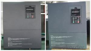
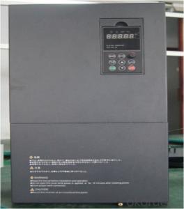
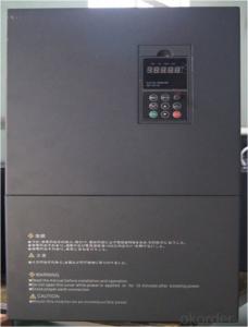
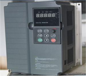
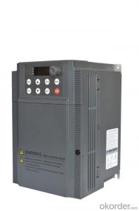
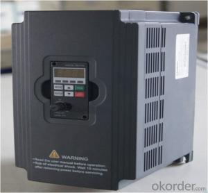
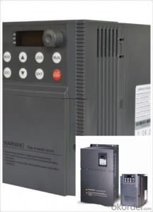
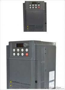
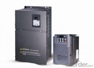
VFD Frequency Drive 3 phase 220V /380V
- Loading Port:
- China Main Port
- Payment Terms:
- TT OR LC
- Min Order Qty:
- -
- Supply Capability:
- -
OKorder Service Pledge
OKorder Financial Service
You Might Also Like
Specifications
1.220V Single Phase Variable Frequency Drive 2.2KW
2.Advanced control technology
3.Easy to operate
220V Single Phase Variable Frequency Drive 2.2KW
General
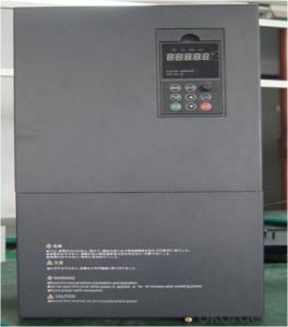
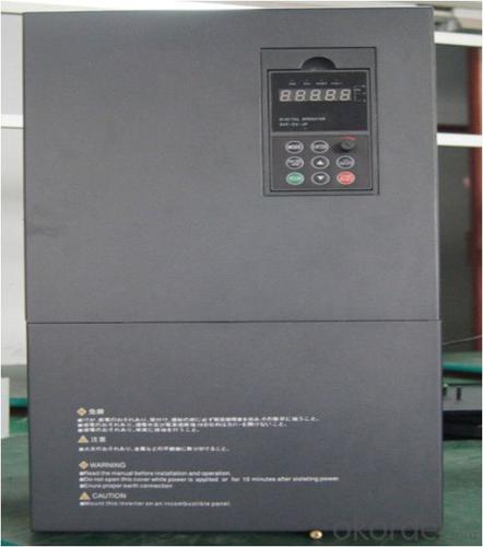
CNBM frequency inverter is a high-quality, multi-function,
low-noise variable frequency drive which is designed, developed and manufactured according to international standards.
It can meet different needs of industrial conditions.
The inverter applies advanced control technology of space voltage vector PWM, with functions of constant voltage control, power-off restart, dead zone compensation, automatic torque compensation, online modification parameter, high-speed impulse input, simple PLC and traverse.
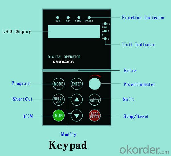
Product Name:CMAX-VCG15/P18.5T3 ~ CMAX-VCG18.5/P22T3
Application
Textile: coarse spinner, spinning frame, wrap-knitting machine, loom, knitting machine, silk-spinning machine, etc.
Plastic: extruder, hauling machine, decorating machine, etc.
Pharmacy: mixer, roaster, etc.
Woodworking: engraving machine, sander, veneer peeling lathe, etc.
Papermaking: single type papermaking machine, etc.
Machine tool: non-core grinding machine, optical lens grinding machine, cutting mill, etc.
Printing: cloth-washing machine, dye vat, etc.
Cement: feeder, air blower, rotary furnace, mixer, crusher, etc
Fan and pump: kinds of fans, blowers and pumps
Specification
Item | Specification | |
Input | Input voltage | 220/380V±15% |
Input frequency | 47~63Hz | |
Output | Output voltage | 0~input voltage |
Output frequency | 0~600Hz | |
Peripheral interface characteristics | Programmable digital input | 4 switch input, 1 high-speed impulse input |
Programmable analog input | AI1: 0~10V input AI2: 0~10V input or 0~20mA input, | |
Programmable open collector output | 2 Output (3.7kW and above: 1 Open collector output) | |
Relay Output | 1 Output (3.7kW and above: 2 Relay output) | |
Analog output | 2 Output, one is 0~10V, another is 0~20mA or 0~10V | |
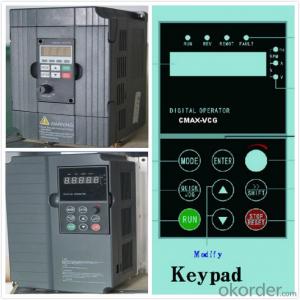
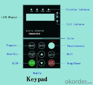
Keypad | Display:5-digit 8-section LED (Red), 2 indicators; parameter setting: 8 keys (including multi-function hot key ), 1 potentiometer | |
Technical performance characteristics | Control mode | All digital space voltage vector SVPWM algorism |
Overload capacity | G purpose: 150% rated current 60s P purpose: 120% rated current 60s | |
Speed ratio | 1: 100 | |
Carrier frequency | 1.0~10.0kHz | |
Torque compensation | Linear, multi-point, 1.3th power, 1.7th power, 2.0th power reduced torque; Compensation voltage range: automatic compensation and manual compensation 0.1~10% | |
Automatic voltage adjustment | It can automatically maintain output voltage constant when grid voltage fluctuates. | |
Automatic current adjustment | When the current is over current limit, under clocking automatically limits output current. | |
Function characteristics | Frequency setting mode | Keypad digital analog input, keypad potentiometer, impulse frequency, communication, multi-step speed and simple PLC, PID setting and so on, switch-over of setting modes. |
Simple PLC, multi-step speed control | 16-step speed control | |
Special function | Traverse control, length control, time control | |
QUICK/JOG key | User-defined multi-function hot key | |
Protection function | Over-current, Over voltage, under-voltage, over-heat, phase failure, over-load and motor over-load | |
Working condition | Installation site | Indoor, altitude of less than 1km, dust free, non-corrosive gases, no direct sunlight |
Application environment | -10°C~+40°C, 20~90%RH (no dew) | |
Vibration | Less than 0.5g | |
Storage temperature | -25°C~+65°C | |
Installation type | Wall-mounted type, floor cabinet type | |
Cooling mode | Air-forced cooling | |
- Q: What does the base frequency 60Hz represent in the inverter?
- For example: if the rated frequency of the motor is 20HZ, the fundamental frequency should be set to 20HZ; if the rated frequency of the motor is 33.3HZ, the fundamental frequency should be set to 33.3HZ; if the rated frequency of the motor is 50HZ, the fundamental frequency should be set to 50HZ; if the rated frequency of the motor is 60HZ, the fundamental frequency should be set to 60HZ; if the rated the working frequency of the motor is 100HZ, the fundamental frequency should be set to 100HZ.
- Q: Where is the difference between soft starter and converter?
- Are two completely different uses of the product. The inverter is used for the need for speed place, its output voltage and frequency change not only change; the soft starter is actually a regulator for motor starting, output voltage and frequency change not only change. Inverters have all of the soft starter functions, but they cost much more than soft starters and have a much more complex structure.
- Q: What does "EPCU" mean in a frequency converter?
- This is the frequency converter BlueOcean Huateng, they said this code external signal interference, you are not the power line and the signal line to go ah, check the external line, then no problem on the phone to the factory
- Q: What are the differences between the two quadrant and the four quadrant of the inverter?
- Simply put, the two quadrant ordinary inverter can only drag the motor forward or reverse. Work in one and three quadrants. The kinetic energy of the motor idle time can only be wasted. (of an electric motor)
- Q: How much is the motor 90KW and the frequency converter selected?Colleagues suggest 110W?The cost will be higherIs it okay to choose 90KW?
- Motor 90KW, frequency converter, 90KW can be applied, but the frequency can not exceed the rated value of the motor. There are some occasions to live and use the frequency converter to speed up the motor, so it should be chosen a little larger, otherwise the inverter will be more loaded.
- Q: What are the parameters of the frequency converter? Thank you
- Some are called bias frequency or frequency offset settings. Its purpose is that when the frequency of external analog signals (voltage or current) to set, you can use this function to adjust the frequency setting signal, minimum output frequency, as shown in figure 1. Some of the inverter when the frequency setting signal is 0%, the error values in the range of 0 ~ Fmax, some converter (such as electricity forhomes Sanken) can also bias polarity settings. For example, in debugging, when the frequency setting signal is 0%, the output frequency of the inverter is not 0Hz, and xHz, then the bias frequency is set to negative xHz, so that the output frequency of the inverter is 0HzI
- Q: Can the motor with frequency converter directly wave the insulation?
- Frequency converter with motor, is a high-power three stage tube, C, E in the output, you directly shake insulation, measuring the pressure of the transistor. So you can't measure it.
- Q: What is the difference between inverter energy consumption braking and motor energy consumption braking?
- Your question, I think it is the difference between regenerative braking and braking of the motor function for active inverter regenerative braking to use inverter feedback power, so there is the braking inverter of the argument?? First of all, define some of your concepts, the motor is divided into reverse braking, energy consumption braking, regenerative braking three. The energy consumption braking of the inverter is called the energy consumption braking by using the braking resistance in the DC loop to absorb the regenerative electric energy of the motor,The utility model has the advantages of simple structure; no pollution to the power grid (for comparison, action and feedback) low cost; the disadvantage is low efficiency, especially to consume a lot of energy and braking resistance will be in frequent braking capacity will increase.
- Q: Can a power converter be used in a motor with small power? Will it burn the motor?
- Large power converter can be used in small power motors, as long as the motor nameplate parameters, in the inverter motor parameters can be set, so that the inverter can provide the right protection.And。 Selection of frequency converter capacity, generally greater than the power of the motor more than one file.
- Q: What are the contents of frequency converter maintenance?
- Operators must be familiar with the basic principles of inverter, functional features, with basic knowledge of electrical operations. Before checking and maintaining the frequency converter, the total power supply of the equipment must be cut off, and the inverter Chang lamp will be completely extinguished.
Send your message to us
VFD Frequency Drive 3 phase 220V /380V
- Loading Port:
- China Main Port
- Payment Terms:
- TT OR LC
- Min Order Qty:
- -
- Supply Capability:
- -
OKorder Service Pledge
OKorder Financial Service
Similar products
Hot products
Hot Searches
