
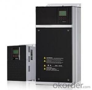
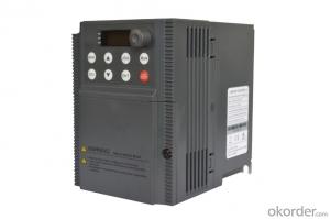
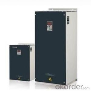
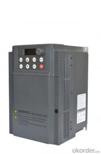
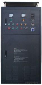
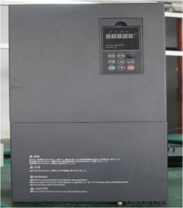
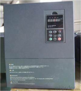
Frequency Inverter Single-phase 380V class 125KW
- Ref Price:
-

- Loading Port:
- Tianjin
- Payment Terms:
- TT OR LC
- Min Order Qty:
- 1 pc
- Supply Capability:
- 100000 pc/month
OKorder Service Pledge
OKorder Financial Service
You Might Also Like


Specifications
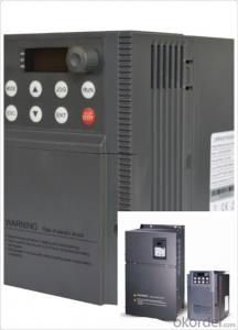
1.380V Single Phase Variable Frequency Drive 125KW
2.Advanced control technology
3.Easy to operate 
General
CNBM frequency inverter is a high-quality, multi-function,
low-noise variable frequency drive which is designed, developed and manufactured according to international standards.
It can meet different needs of industrial conditions.
The inverter applies advanced control technology of space voltage vector PWM, with functions of constant voltage control, power-off restart, dead zone compensation, automatic torque compensation, online modification parameter, high-speed impulse input, simple PLC and traverse.
Product Name:CMAX-VCG15/P18.5T3 ~ CMAX-VCG18.5/P22T3
Application
Textile: coarse spinner, spinning frame, wrap-knitting machine, loom, knitting machine, silk-spinning machine, etc.
Plastic: extruder, hauling machine, decorating machine, etc.
Pharmacy: mixer, roaster, etc.
Woodworking: engraving machine, sander, veneer peeling lathe, etc.
Papermaking: single type papermaking machine, etc.
Machine tool: non-core grinding machine, optical lens grinding machine, cutting mill, etc.
Printing: cloth-washing machine, dye vat, etc.
Cement: feeder, air blower, rotary furnace, mixer, crusher, etc
Fan and pump: kinds of fans, blowers and pumps
Specification
Item | Specification | |
Input | Input voltage | 220/380V±15% |
Input frequency | 47~63Hz | |
Output | Output voltage | 0~input voltage |
Output frequency | 0~600Hz | |
Peripheral interface characteristics | Programmable digital input | 4 switch input, 1 high-speed impulse input |
Programmable analog input | AI1: 0~10V input AI2: 0~10V input or 0~20mA input, | |
Programmable open collector output | 2 Output (3.7kW and above: 1 Open collector output) | |
Relay Output | 1 Output (3.7kW and above: 2 Relay output) | |
Analog output | 2 Output, one is 0~10V, another is 0~20mA or 0~10V | |
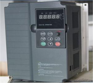
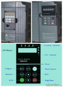
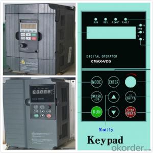
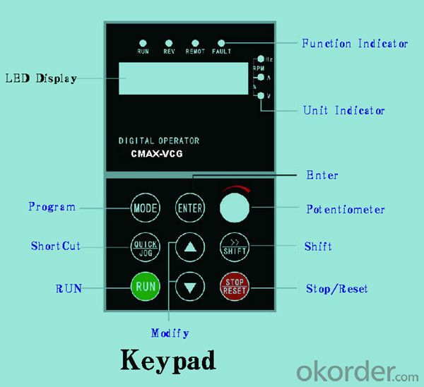
Keypad | Display:5-digit 8-section LED (Red), 2 indicators; parameter setting: 8 keys (including multi-function hot key ), 1 potentiometer | |
Technical performance characteristics | Control mode | All digital space voltage vector SVPWM algorism |
Overload capacity | G purpose: 150% rated current 60s P purpose: 120% rated current 60s | |
Speed ratio | 1: 100 | |
Carrier frequency | 1.0~10.0kHz | |
Torque compensation | Linear, multi-point, 1.3th power, 1.7th power, 2.0th power reduced torque; Compensation voltage range: automatic compensation and manual compensation 0.1~10% | |
Automatic voltage adjustment | It can automatically maintain output voltage constant when grid voltage fluctuates. | |
Automatic current adjustment | When the current is over current limit, under clocking automatically limits output current. | |
Function characteristics | Frequency setting mode | Keypad digital analog input, keypad potentiometer, impulse frequency, communication, multi-step speed and simple PLC, PID setting and so on, switch-over of setting modes. |
Simple PLC, multi-step speed control | 16-step speed control | |
Special function | Traverse control, length control, time control | |
QUICK/JOG key | User-defined multi-function hot key | |
Protection function | Over-current, Over voltage, under-voltage, over-heat, phase failure, over-load and motor over-load | |
Working condition | Installation site | Indoor, altitude of less than 1km, dust free, non-corrosive gases, no direct sunlight |
Application environment | -10°C~+40°C, 20~90%RH (no dew) | |
Vibration | Less than 0.5g | |
Storage temperature | -25°C~+65°C | |
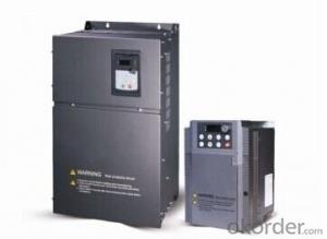
Installation type | Wall-mounted type, floor cabinet type | |
Cooling mode | Air-forced cooling | |
- Q: At the base block Yaskawa inverter is what reason?
- This is the base block command, when the external input block command signal, the frequency converter will appear this code, the emergence of this code, the motor will rotate freely, does not affect the use.
- Q: When the inverter is running at full 50HZ, the output voltage decreases and the output current becomes smaller. What is the reason?
- If the load of the motor is increased, the slip S is increased, the electromotive force of the motor is decreased, and the electric current of the motor will become larger. That is to say, when the motor is running in the overclocking stage, the load of the motor is light, the current will become smaller, and the current will not be smaller if the load is negative. Didn't I make myself clear?
- Q: Where is the difference between soft starter and converter?
- High voltage soft starter work in high voltage environment, the insulation performance of all kinds of electrical components must be better, and the anti-interference ability of electronic chip is stronger. When the high voltage soft starter is composed of an electric cabinet, the layout of the electrical components and the connection with the high voltage soft starter and other electrical equipment are also very important.
- Q: What is frequency conversion? What is the function of frequency converter?
- Frequency conversion:1, the frequency conversion is to change the power supply frequency, thus adjust the load, play a role in reducing power consumption, reducing the loss and prolonging the service life of the equipment. Frequency conversion.2, the core of frequency conversion technology is frequency converter, through the power frequency conversion to achieve automatic adjustment of motor speed rate, the fixed frequency of 50Hz is changed to 30 - 130 Hz frequency. At the same time, the utility model makes the voltage range of the supply voltage reach 142 - 270V, and solves the problem that the voltage of the power grid is unstable, which influences the work of the electric appliance. The technique of alternating current control by changing the frequency of alternating current is called frequency conversion technology.
- Q: What is the upper and lower limit of the environmental temperature to ensure the normal operation of the inverter?
- General environment temperature: inverter is an electronic device, containing electronic components, electrolytic capacitors, etc., so the temperature has a greater impact on its life. The environment of general inverter operating temperature of ~+50 DEG C - General requirements, if it can reduce the operation temperature of inverter, prolongs the service life of the transducer, stable performance. So heat dissipation is very important.
- Q: Why does the frequency change when the frequency converter regulates the frequency?
- That's for sure. The curve of voltage and frequency should be set according to the load condition, but after the rated frequency of the motor, the voltage is kept at the rated voltage
- Q: How do two inverters synchronize?
- Higher requirements, you can use 2 of the method, the middle of which potentiometer into a dedicated proportional controller. More secure and reliable, and the proportion can be adjusted precisely in 0--200%
- Q: Why does harmonic generator produce harmonic? What's his working principle?
- The harmonic generation mechanism of frequency converter is because of the non-linearity of frequency converter, including two parts: rectifier and inverter. For a simple example, the streams we see are, if there is no wind, and the bottom is flat, then there will be no waves, no ripples. This is because the water flows through the region is linear. Because of the fact that the wind and the water are not flat enough, these nonlinear conditions lead to waves and ripples.
- Q: Does the number of inverter settings differ from the number of motor poles, and does it affect the use?
- The influence of the inverter on the motor control model, in addition to the speed difference, basically does not affect much
- Q: What is the over-current of the inverter?
- Inverter hardware problems:?(1) the current transformer is damaged. The phenomenon is that the main circuit of the converter sends power. When the converter is not started, the current is displayed and the current is changing, so that the transformer is damaged.?(2) the main circuit interface board, the current and voltage detection channels are damaged, and there will be over-current. The damage to the circuit board may be:?Because of the poor environment, conductive solid particles are attached to the circuit board to cause electrostatic damage. Or corrosive gases that cause the circuit to corrode.?Zero potential circuit board and the casing are connected together, the cabinet and the angle of welding, a powerful arc, will affect the performance of circuit board.?Due to poor grounding, the circuit board zero volts interference, it will cause damage to the circuit board.?(3) because the connection plug is not tight and unstable. For example, the current or voltage feedback signal line is not in good contact, and sometimes the over-current fault occurs.
Send your message to us
Frequency Inverter Single-phase 380V class 125KW
- Ref Price:
-
- Loading Port:
- Tianjin
- Payment Terms:
- TT OR LC
- Min Order Qty:
- 1 pc
- Supply Capability:
- 100000 pc/month
OKorder Service Pledge
OKorder Financial Service
Similar products

Hot products


Hot Searches
Related keywords

