
China VFD Frequency Drive 3 phase 220V 380V
- Ref Price:
-

- Loading Port:
- Tianjin
- Payment Terms:
- TT OR LC
- Min Order Qty:
- 1 pc
- Supply Capability:
- 100000 pc/month
OKorder Service Pledge
OKorder Financial Service
You Might Also Like


General
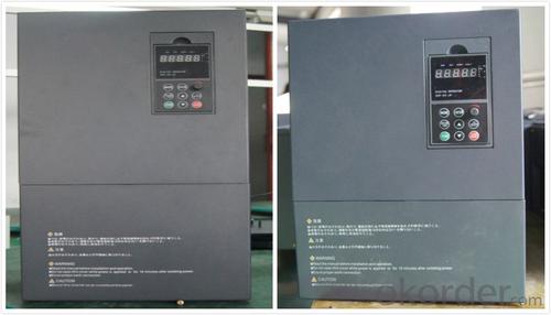
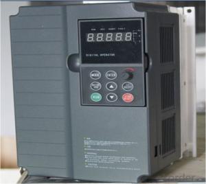
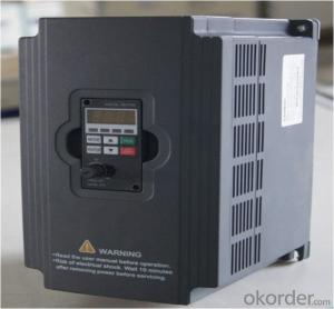
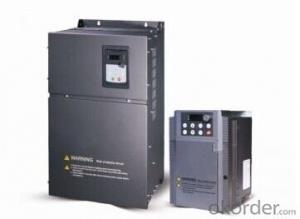
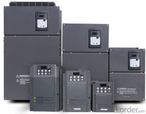
CNBM frequency inverter is a high-quality, multi-function,
low-noise variable frequency drive which is designed, developed and manufactured according to international standards.
It can meet different needs of industrial conditions.
The inverter applies advanced control technology of space voltage vector PWM, with functions of constant voltage control, power-off restart, dead zone compensation, automatic torque compensation, online modification parameter, high-speed impulse input, simple PLC and traverse.
Application
Textile: coarse spinner, spinning frame, wrap-knitting machine, loom, knitting machine, silk-spinning machine, etc.
Plastic: extruder, hauling machine, decorating machine, etc.
Pharmacy: mixer, roaster, etc.
Woodworking: engraving machine, sander, veneer peeling lathe, etc.
Papermaking: single type papermaking machine, etc.
Machine tool: non-core grinding machine, optical lens grinding machine, cutting mill, etc.
Printing: cloth-washing machine, dye vat, etc.
Cement: feeder, air blower, rotary furnace, mixer, crusher, etc
Fan and pump: kinds of fans, blowers and pumps
Specification
Item | Specification | |
Input | Input voltage | 220/380V±15% |
Input frequency | 47~63Hz | |
Output | Output voltage | 0~input voltage |
Output frequency | 0~600Hz | |
Peripheral interface characteristics | Programmable digital input | 4 switch input, 1 high-speed impulse input |
Programmable analog input | AI1: 0~10V input AI2: 0~10V input or 0~20mA input, | |
Programmable open collector output | 2 Output (3.7kW and above: 1 Open collector output) | |
Relay Output | 1 Output (3.7kW and above: 2 Relay output) | |
Analog output | 2 Output, one is 0~10V, another is 0~20mA or 0~10V | |
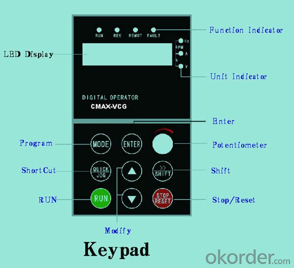
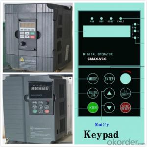
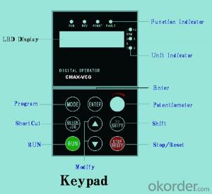
Keypad | Display:5-digit 8-section LED (Red), 2 indicators; parameter setting: 8 keys (including multi-function hot key ), 1 potentiometer | |
Technical performance characteristics | Control mode | All digital space voltage vector SVPWM algorism |
Overload capacity | G purpose: 150% rated current 60s P purpose: 120% rated current 60s | |
Speed ratio | 1: 100 | |
Carrier frequency | 1.0~10.0kHz | |
Torque compensation | Linear, multi-point, 1.3th power, 1.7th power, 2.0th power reduced torque; Compensation voltage range: automatic compensation and manual compensation 0.1~10% | |
Automatic voltage adjustment | It can automatically maintain output voltage constant when grid voltage fluctuates. | |
Automatic current adjustment | When the current is over current limit, under clocking automatically limits output current. | |
Function characteristics | Frequency setting mode | Keypad digital analog input, keypad potentiometer, impulse frequency, communication, multi-step speed and simple PLC, PID setting and so on, switch-over of setting modes. |
Simple PLC, multi-step speed control | 16-step speed control | |
Special function | Traverse control, length control, time control | |
QUICK/JOG key | User-defined multi-function hot key | |
Protection function | Over-current, Over voltage, under-voltage, over-heat, phase failure, over-load and motor over-load | |
Working condition | Installation site | Indoor, altitude of less than 1km, dust free, non-corrosive gases, no direct sunlight |
Application environment | -10°C~+40°C, 20~90%RH (no dew) | |
Vibration | Less than 0.5g | |
Storage temperature | -25°C~+65°C | |
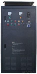
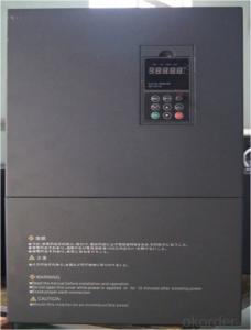
Installation type | Wall-mounted type, floor cabinet type | |
Cooling mode | Air-forced cooling | |
- Q: High-voltage converterGeneral inverterPump frequency converterEngineering frequency converterCould you tell me some frequency converter according to the class?
- Specific answer to your question: 1, high voltage inverter: This is based on the input voltage level terms. Generally speaking, 10KV is more than 6KV voltage high voltage frequency converter, 1140V, 3300V in general is medium (some people also called it the high voltage level of 380V, 660V), 480V, commonly called the low-voltage inverter; 2, pump inverter: This is according to the type of application in terms of. Fan pump inverter mainly refers to the frequency converter used to drag fans, pump load, the main feature is light load, simple application.
- Q: The frequency converter is in use suddenly the speed reduces, then the debugging is out of control, how to do?
- Overvoltage prevention measures: due to over-voltage causes are different, so the countermeasures are not the same. For overvoltage in parking, if there is no special requirement for parking time or position, it can be solved by using extended frequency converter, deceleration time or free parking. The so-called free parking, that is, the frequency converter will switch off the main switch, so that the motor free sliding stop. If the parking time or parking position have certain requirements, then the DC brake (DC brake) function can be used
- Q: What is the difference between frequency converter and servo driver?
- The difference between servomotor and frequency conversion motor:Servo system is a closed-loop control system, the inverter usually works in open-loop control, so in terms of speed and accuracy, and can not be compared to the servo drive.The frequency conversion is only one part of the servo, and the servo controls the closed loop precisely on the basis of frequency conversion so as to achieve better results.
- Q: How do you understand the ramp up (descent) time of the inverter? Thank you!
- The ramp up time is to start from the 0 speed, inverter, running to reach the given speed (for example: 1420) the time required, in general, the longer the time, the frequency converter and motor impact is small. In the actual work process, according to process requirements to set the length of time. (more than 10-15 seconds) or so, if it is a pump or fan motor, do not need to change its rise time, the default can.
- Q: Where is the frequency converter used?
- The machinery manufacturing industry, including: elevator, automobile, textile, printing and packaging, paper making, hoisting machinery, food, tobacco, etc. the use of these pumps, inverter industry is mainly in electrical equipment, control and obtain the best product performance and output rate is the main purpose of energy saving is different from the 1 in
- Q: What does the RUN key on the inverter mean? How do you use it?
- According to the actual needs of the motor to provide the required power supply voltage, and then to achieve energy saving, speed control purposes, in addition, there are many inverter protection functions, such as over-current, overvoltage, overload protection, etc.. With the continuous improvement of the degree of industrial automation, inverter has also been widely used.
- Q: PT100 temperature patrol instrument, when the converter is not open, the measurement is normal. Once opened, it shows completely disorder, and sometimes there are puzzling characters. How can I solve this problem? Please enlighten master!
- In the complex electromagnetic environment, AnyWay advocates the idea of digital front end, that is, in the vicinity of being measured, the signal will be digitized, and then the uploaded information will be uploaded to the host computer through digital communication. Digital transmission is much better than analog transmission in anti-interference ability. If the electromagnetic interference is very large, the transmission line can be changed into optical fiber transmission. In this way, the transmission link can completely avoid interference.
- Q: What is the difference between SIEMENS inverter and built-in filter?
- The filter is used for electromagnetic interference protection. Not only for the protection of electrical equipment, but also for the use of environmental protection. Inverter application environment is very extensive. Industry, light industry, commerce, civil, etc.. So the level of electromagnetic protection is also different.By the way。 If you disconnect the converter. See a coil on a board. That's the built-in filter. If you don't have it, you don't have that coil.
- Q: If you don't plug in the PG card, do you use PLC's PID control?Plug in the PG card and the PLC PID control, which is reliable and precise?
- There are several kinds of closed loop, speed closed loop, temperature / pressure / flow closed loop.Since you're talking about PG cards, then obviously you have to control speed.Generally speaking, the control precision is related to the hardware, and the PLC can also output pulses.If you are small system, simple control, it is recommended that you use PG card + encoder to save the cost, you can inverter internal PID, and control accuracy is also ok.My feeling, as if the speed control precision is high, is PG card.
- Q: What does "G" and "P" mean in the converter model?
- General inverter said, "G" and "P" type refers to the inverter general type and fan pump difference, G type inverter applies to the general machinery class load, and P type is used in the wind or water pump.
Send your message to us
China VFD Frequency Drive 3 phase 220V 380V
- Ref Price:
-
- Loading Port:
- Tianjin
- Payment Terms:
- TT OR LC
- Min Order Qty:
- 1 pc
- Supply Capability:
- 100000 pc/month
OKorder Service Pledge
OKorder Financial Service
Similar products

Hot products

Hot Searches

