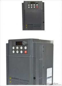
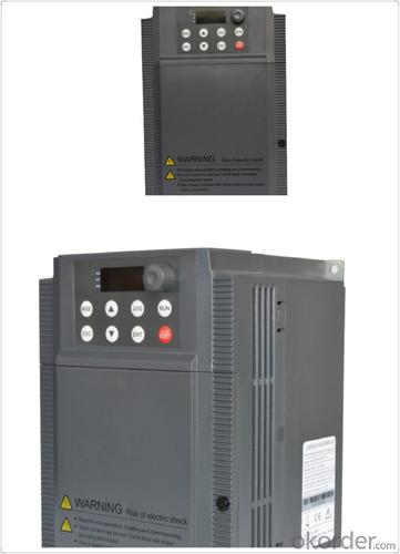
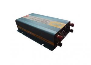
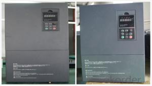
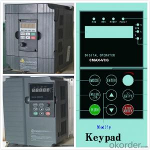
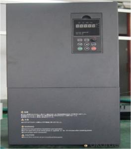
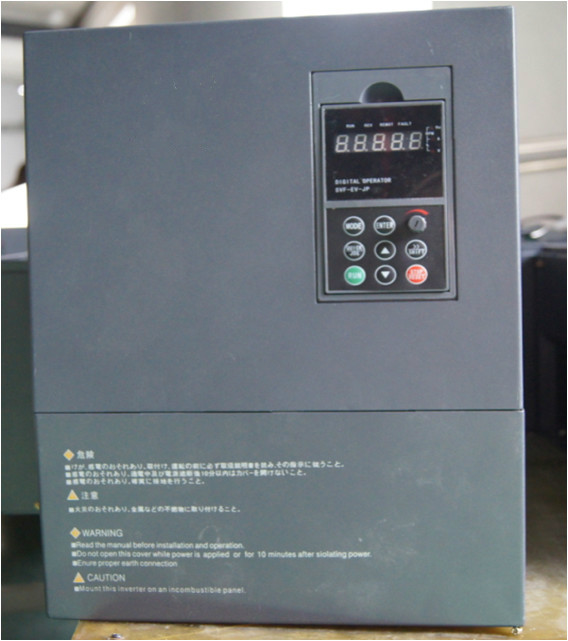
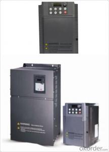
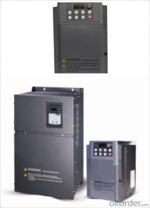
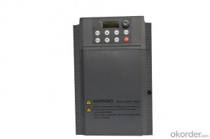
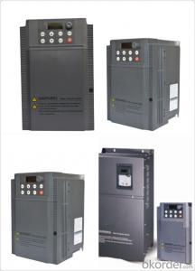
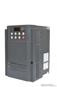
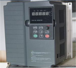
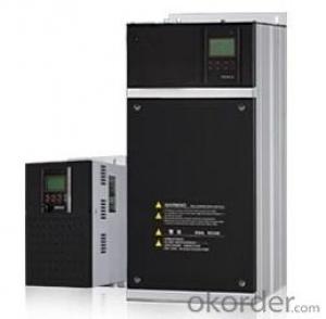
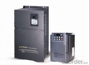
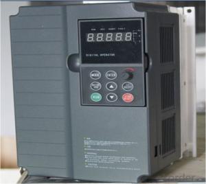
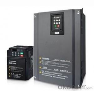
Frequency Inverter Single-phase 220V class 1.2KW
- Loading Port:
- Tianjin
- Payment Terms:
- TT OR LC
- Min Order Qty:
- 1 pc
- Supply Capability:
- 100000 pc/month
OKorder Service Pledge
OKorder Financial Service
You Might Also Like
Specifications
1.220V Single Phase Variable Frequency Drive 2.2KW
2.Advanced control technology
3.Easy to operate
General
CNBM frequency inverter is a high-quality, multi-function,
low-noise variable frequency drive which is designed, developed and manufactured according to international standards.
It can meet different needs of industrial conditions.
The inverter applies advanced control technology of space voltage vector PWM, with functions of constant voltage control, power-off restart, dead zone compensation, automatic torque compensation, online modification parameter, high-speed impulse input, simple PLC and traverse.
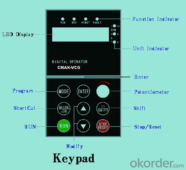
Product Name:CMAX-VCG15/P18.5T3 ~ CMAX-VCG18.5/P22T3
Application
Textile: coarse spinner, spinning frame, wrap-knitting machine, loom, knitting machine, silk-spinning machine, etc.
Plastic: extruder, hauling machine, decorating machine, etc.
Pharmacy: mixer, roaster, etc.
Woodworking: engraving machine, sander, veneer peeling lathe, etc.
Papermaking: single type papermaking machine, etc.
Machine tool: non-core grinding machine, optical lens grinding machine, cutting mill, etc.
Printing: cloth-washing machine, dye vat, etc.
Cement: feeder, air blower, rotary furnace, mixer, crusher, etc
Fan and pump: kinds of fans, blowers and pumps
Specification
Item | Specification | |
Input | Input voltage | 220/380V±15% |
Input frequency | 47~63Hz | |
Output | Output voltage | 0~input voltage |
Output frequency | 0~600Hz | |
Peripheral interface characteristics | Programmable digital input | 4 switch input, 1 high-speed impulse input |
Programmable analog input | AI1: 0~10V input AI2: 0~10V input or 0~20mA input, | |
Programmable open collector output | 2 Output (3.7kW and above: 1 Open collector output) | |
Relay Output | 1 Output (3.7kW and above: 2 Relay output) | |
Analog output | 2 Output, one is 0~10V, another is 0~20mA or 0~10V | |
Keypad | Display:5-digit 8-section LED (Red), 2 indicators; parameter setting: 8 keys (including multi-function hot key ), 1 potentiometer | |
Technical performance characteristics | Control mode | All digital space voltage vector SVPWM algorism |
Overload capacity | G purpose: 150% rated current 60s P purpose: 120% rated current 60s | |
Speed ratio | 1: 100 | |
Carrier frequency | 1.0~10.0kHz | |
Torque compensation | Linear, multi-point, 1.3th power, 1.7th power, 2.0th power reduced torque; Compensation voltage range: automatic compensation and manual compensation 0.1~10% | |
Automatic voltage adjustment | It can automatically maintain output voltage constant when grid voltage fluctuates. | |
Automatic current adjustment | When the current is over current limit, under clocking automatically limits output current. | |
Function characteristics | Frequency setting mode | Keypad digital analog input, keypad potentiometer, impulse frequency, communication, multi-step speed and simple PLC, PID setting and so on, switch-over of setting modes. |
Simple PLC, multi-step speed control | 16-step speed control | |
Special function | Traverse control, length control, time control | |
QUICK/JOG key | User-defined multi-function hot key | |
Protection function | Over-current, Over voltage, under-voltage, over-heat, phase failure, over-load and motor over-load | |
Working condition | Installation site | Indoor, altitude of less than 1km, dust free, non-corrosive gases, no direct sunlight |
Application environment | -10°C~+40°C, 20~90%RH (no dew) | |
Vibration | Less than 0.5g | |
Storage temperature | -25°C~+65°C | |
Installation type | Wall-mounted type, floor cabinet type | |
Cooling mode | Air-forced cooling | |
- Q: Frequency converter, fault, contact action
- Frequency converter is the application of frequency conversion technology and micro electronics technology, by changing the power supply frequency of the motor to control AC motor power control equipment. The frequency converter is mainly composed of rectifier (AC DC converter), filter, inverter (DC AC converter), brake unit, drive unit, detection unit, micro processing unit and so on. Inverter by internal IGBT drive voltage and frequency off to adjust the output power, the power supply voltage required to provide according to the actual needs of the motor, so as to achieve the purpose of speed, energy saving, in addition, there are a lot of protection drive, such as over-current, over-voltage, overload protection and so on. With the continuous improvement of the degree of industrial automation, inverter has also been widely used.
- Q: What's the use of switching frequency of converter?
- Very important!The higher the switching frequency is, the smaller the harmonic is when the output waveform passes through the motor winding. The reason is that the higher the switching frequency is, the higher the harmonic frequency is, the higher the harmonic impedance is, and the smaller the harmonic current is. The smaller the harmonic current is, the smaller the harmonic loss is and the smaller the torque ripple is, the better the motor performance is.However, the higher the switching frequency, the greater the frequency converter loss, the lower the efficiency of the inverter, and more importantly, the greater the heat, the inverter may not be able to bear.In addition, according to the fundamental frequency of operation, the switching frequency is preferably an integer multiple of the fundamental frequency, and this multiple is an integer multiple of 3, which can effectively reduce the low harmonics which affect the motor greatly!
- Q: That is, some parameters of the inverter, such as torque, current, frequency, etc., are displayed on the Kingview software interface, but not through the PLC. The idea that the MODBUS protocol between SIEMENS and 200PLC has never been successful before, so that's the idea of the ABB. If it can be achieved,Is it necessary to write the script program on the Kingview, and what problems should I pay attention to when using the MODBUS protocol in Kingview software?The problem is a little bit more, I hope the experts teach me this rookie! Thank you
- As long as there are 485 communications can be, the frequency converter manual on the MODBUS protocol, the address of each parameter, in the king view on the link can do, and I hope to adopt.
- Q: It was when processing a workpiece, processing spindle stops suddenly (other are normal) a check is, I jump out of the inverter, I can click on a processing, and then processing not long after they happen, (do not open the machine spindle machining will also be the case)
- It should be a frequency converter. Right now, look at the frequency converter output frequency settings, tune, and suggest the next election wide output frequency converter, or simply PLC
- Q: Ask, what is the ratio of frequency converter?
- Connect the air switch, the power supply, check the wiring is correct, close the air switch, turn on the frequency converter, and the digital tube shows 0.Turn off the power, the power indicator light is extinguished, then connect the motor, on-off switch, tone potentiometer, trimmer potentiometer, inching button, frequency meter (0 ~ 10V voltage meter), three sets of inverter and motor proportion of joint operation, the inverter and the motor grounding terminal reliable grounding, and carefully check.
- Q: Why does the frequency change when the frequency converter regulates the frequency?
- That's for sure. The curve of voltage and frequency should be set according to the load condition, but after the rated frequency of the motor, the voltage is kept at the rated voltage
- Q: Why do you install these things? Our factory has 380220 points. Then we plant in addition to high voltage motor, the other are 380 of the motor, then what's the use of these two things?
- Asynchronous motor is the torque between the current flowing through the motor flux and rotor as a result of the interaction, at rated frequency, but only if the voltage will reduce the frequency, then the magnetic flux on a large magnetic circuit saturation, the motor will be seriously burned. Therefore, the frequency and voltage should be changed proportionally, that is to say, to change the frequency, to control the output voltage of the converter at the same time, to keep the flux of the motor to be certain, and to avoid the occurrence of the weakening of the magnetic flux and the saturation of the magnetic flux. This control mode is mostly used in fans, pumps and energy saving inverters. The frequency changer changes the voltage, must change the frequency
- Q: There is much dust and moisture in my workshop. Many brands are not durable.
- ABB inverter is of high quality, but it requires a lot of environment, such as dust and humidity in your workshop. It is too bad for ABB inverters. You can try to use the seal of inverter, it is designed according to the use environment of inverter in various industries, mainly considering China's current converter relatively harsh environment (water vapor, dust, oil, metal powder, corrosive gas), in CNC lathe, grinding machine chemical plant, reaction kettle, blender, textile machinery, printing and dyeing equipment, water pump, industrial washing machine, dehydration machine where the effect is very good.
- Q: Frequency converter OC alarm, what's the matter?
- And some did not inform you of the inverter fault category, when the OC boot failure, will cause greater danger, then simply caused by surface phenomenon similar to program crashes, such as the P9/G9 series machine when the machine detects INVT, module failure, operationThe H00 character appears on the panel, and all key actions are rejected. Unknown insider will think: program crash, CPU motherboard is a problem.
- Q: What do you mean by the capacity of the inverter and the capacity of the motor?
- Because the motor consumes active power and consumes reactive power, and the reactive power is also occupied, the motor with 70KW can only be usedThe power is known to everyone
Send your message to us
Frequency Inverter Single-phase 220V class 1.2KW
- Loading Port:
- Tianjin
- Payment Terms:
- TT OR LC
- Min Order Qty:
- 1 pc
- Supply Capability:
- 100000 pc/month
OKorder Service Pledge
OKorder Financial Service
Similar products
Hot products
Hot Searches
Related keywords
