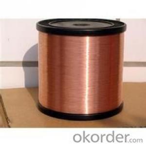
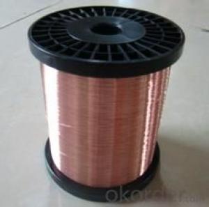
Tinned Copper Clad Aluminum Magnesium Wire
- Loading Port:
- China Main Port
- Payment Terms:
- TT or LC
- Min Order Qty:
- -
- Supply Capability:
- -
OKorder Service Pledge
OKorder Financial Service
You Might Also Like
1.Product Description:
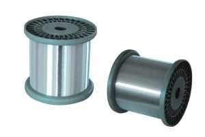
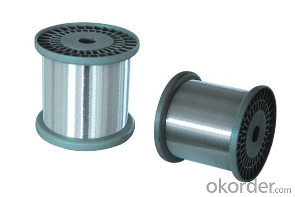
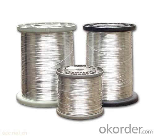
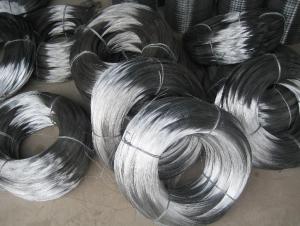
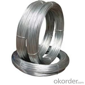
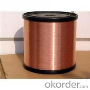
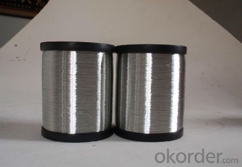
Tinned CCAM wire with CCAM core , then painted with the Tin layer , it’s a new shielding material
which combines the good conductivity of copper and light weight of aluminum . It is good at shielding ,
easy welding and not easy to oxidation .
2. Product Characteristic:
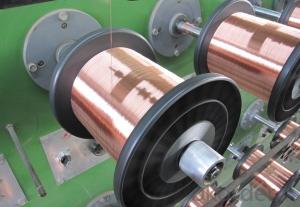
1. Used for producing braiding wire , which suit for flexible connections of electrical installation ,
switching device .
2. Used for production of the wave-proof cover, which suit for prevent radio frequency interference
or protection of shielding copper braided cover .
3.Specification :
Diameter: 0.12mm--0.80mm
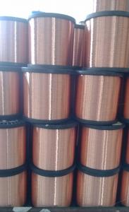
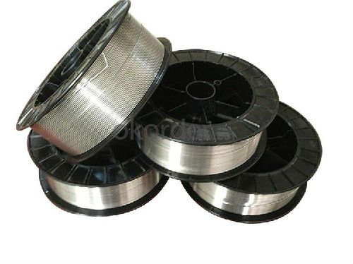
Normal Package:roll
Spool size : DIN130mm,DIN180mm, DIN250mm, DIN400mm
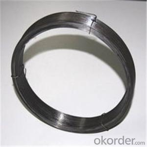
4. Reference Picture:

- Q: i have just got a radio from a 2004dodge durango my buddy bought a new radio and i tok his old one, so now i need the wiring diagram to find out what all the wires goo too their are way more wires on thios thing that im use to on stock radios. ive looked it up online and its not the right diagrams the colors dont match up on the wires. ny help pleaseeee
- check out the link this is where i always go and always im able to find the car listing im looking for goodluck!
- Q: my husband is running wire to a hot tub, which uses a 220 plug. he is going to hook up a 30 amp breaker. what size wire should be used?
- First thing you need to do is call your city's building inspectors and get necessary permits. !!! For your protection. #10 wire for thirty amp breaker. For 220VAC you will need 3 wire (three conductor cables) plus ground wire for a thirty amp breaker. But question is what is the ampacity rating of your hot tub? You need to size your circuit breaker to the ampacity of your hot tub. Breaker is going to have to be a two pole (double pole) breaker GFCI breaker since it is 220 VAC. since it is for a hot tub. You should have a red wire a black wire a white wire and a bare wire in your cable. The black wire and red wire are your hot wires they go to the breaker. The white wire is your neutral (grounded conductor) it goes to the terminal strip where all the other neutral wires are connected in the breaker box. The bare wire is your ground wire! It goes to the ground wire terminal strip in the breaker box. Now that said if you or your husband is not absolutely sure about what you are doing get an electician to do it for. First water and electricity do not mix at all good together. Good way to get fried if tub goes hot on you if hooked up wrong. Good way to burn the house down if hooked up wrong as well. Another thing since it is a hot tub meaning like wet area like bathrooms and out side special considerations are going to have to be taken for safety namely you are going to have to use a GFCI circuit breaker or have a GFCI double pole switch to disconnect the tub incase of a short circuit or excessive current leakage to ground otherwise you end up bolied lobsters. Well done and ready to eat by the time you are found. Not as easy as just hooking up three wires is it. And if you do not know exaclty what you are doing call an electrician.
- Q: Found some electrical wiring resonably priced on craigslist but it says -----8 gauge (AWG), 3 wire, direct burry electrical cableDOES THAT MEAN ITS 3/0 WIRE? Because I need 3/0 wire direct burriedI am looking to buy some extra 3/0 wire and found some on craigslist for a reasonable price..
- By code, if you use direct burial cable, you'll have to bury the cable deeper than you would if it were in conduit (PVC). There are several different factors that determine how deep you need to go if direct burial is what you're going to stick with. The voltage your supplying, is it covered by soil only, will it be paved over or covered with a concrete surface for any reason, etc. 23 yr journeyman electrician.
- Q: I am planning to wire my single sub 400rms svc to my amplifier 400rms x 1 @4 ohms. My car model is 94 mitsubishi lancer. how many AWG ( gauge) should I use? Like for Power, ground, speaker wire. I just want to have the full potential of my sub and ampli.For my 2nd question: if I decided to put a 2nd sub wired it on the same amp making it 800rms x1 @ 2 ohms. (my amplifier is a class d mono 1600 watt peak by the way) should I need to use a capacitor?Thank you
- wire okorder /
- Q: I have an immersion heater in my hot water cylinder (UK airing cubbard), but the wiring isn't connected. But, I seem to be missing a small piece or two. The previous lead wire from the timer/switch is stil there and has two wires in it. Does someone have a generic wiring digram showing which wires connect to the thermostat and which wires connect to the heating element? Thanks!
- Normal wiring with two connections on thermostat, on from timer and two on element would be a single wire from one of the timer wires to one connection on thermostat, one wire from other connection on thermostat to heater connection, then one wire from other heater connection back to remaining connection on timer. This is if the thermostat is high voltage and not a low voltage signal to a controller perhaps on the timer.
- Q: there is different gauge wire sizes in the power/ground and speaker wire? which is better? what is the difference? buy ground power and speaker wire the same gauge?
- Use the 4 gauge wire (thicker) for your power and then the 8 gauge wire for speakers and ground. If you are wiring a stereo with an amp, its best to ground both at the same spot to reduce what is called ground loop. Otherwise, you may hear engine noise through your speakers and possibly clicks when using your turn signals.
- Q: what is the best wire to use for a chainmail
- If you plan to wear this, stainless steel is the only wire that will not rust. Knights look terrible with underarm rusty mail.
- Q: Why does a thin wire melt and a thick wire glow when put up to the terminals? Explain in terms of resistance and current. Thanks=]
- the electrical restistance of a thin wire is greater that the tick wire. thus : Watt = current * current * resistance if the resistance of the thick wire is 10 times the resistcance of the thin wire , then ( with same voltage ) you have for small wire Watt = current * current * resistance for thick wire Watt = 10*current * 10*current * (resistance/10) = 10current current resistance. so the power generated in the thick wire is ten times more than the power in the thin wire ( if you keep the voltage the same ) so that is not why the smaller one melts. I dont know why it melts then, interesting
- Q: it still has the harness but im not sure which wires are what and its a 14 pin connector
- Do okorder You can also get install kits.
- Q: My home is wired for the thermostats with two wires (red and white). I have acquired a new thermostat that requires a Red, White, and Common wire. Using the white wire in that position will power the unit up but it won't trigger the heat. Is there something that can be put in line that will allow this thermostat to work without rewiring the house?
- T-stat wires are usually left loose in the wall, no staples, so you can easily replace it by pulling a new wire through with the old one. First try to get an idea of where the wire goes. Get an estimate of total length and go to home depot and purchase 18-3 t-stat wire. They sell it in 25 feet, 50 feet, 100 feet, 500 feet, or by the foot. Compare prices and get enough to make a continuous run. Older 2 wire Tstats used a mercury or spring switch to simply connect the two wires together (24v + and sl return). Your new Tstat needs a common because it is being powered by the same feed that activates the unit. (So you have 24+ 24- and sl return) When you attach your new wire to your old wire be sure to actually strip the outer coating of about 4 inches or so and fold the wires around each other to get a good strong bond, and then tape it tight to keep it as small diameter as possible.
Send your message to us
Tinned Copper Clad Aluminum Magnesium Wire
- Loading Port:
- China Main Port
- Payment Terms:
- TT or LC
- Min Order Qty:
- -
- Supply Capability:
- -
OKorder Service Pledge
OKorder Financial Service
Similar products
Hot products
Hot Searches
Related keywords
