

Round Copper Aluminum Magnesium Alloy Wire
- Ref Price:
-

- Loading Port:
- China main port
- Payment Terms:
- TT OR LC
- Min Order Qty:
- 10 m.t.
- Supply Capability:
- 1000 m.t./month
OKorder Service Pledge
OKorder Financial Service
You Might Also Like


1.Features of copper clad aluminum magnesium alloy wire:
Specifications: 0.08-3.2mm
Status: H112
Hardness (500kg force 10mm ball): 70-85
Tensile strength (25 ℃ when MPa): 180
The yield strength (25 ℃ when MPa): 211
Melting range (℃): 570-640
Conductivity (20 ℃ pm): 29% IACS
2.Introduction of copper clad aluminum magnesium alloy wire:
Aluminum-magnesium alloy wire is high strength low alloy steel, heat treatment has good mechanical properties, high strength, sufficient toughness, hardenability, weldability (preheat), processing formability are good, but the resistance low corrosion resistance and oxidation resistance, usually after quenching and tempering or isothermal use. High strength quenched and tempered steel. Has high strength and toughness, high hardenability, cold plastic deformation moderate, good cutting performance.
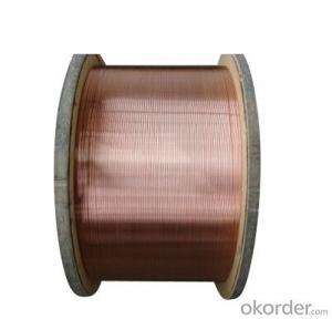
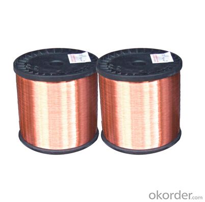
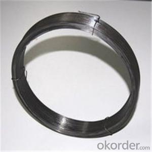
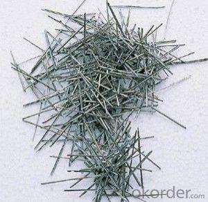
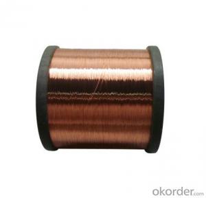
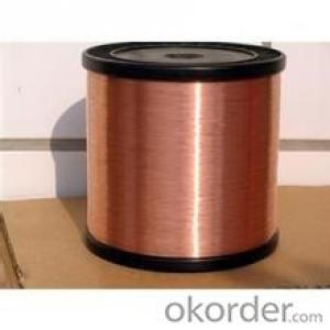
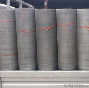
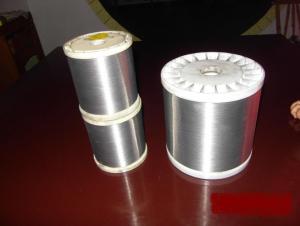
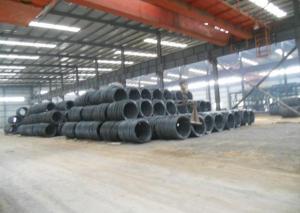
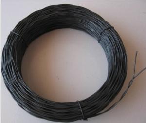
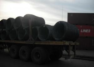
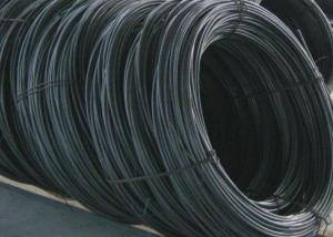
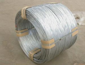
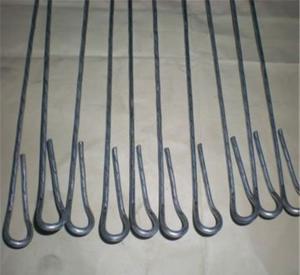
3.Image of copper clad aluminum magnesium alloy wire:

4.Technical parameters: of copper clad aluminum magnesium alloy wire:
Name | single crystal Copper Wire | ||
Model number | 1701 | ||
Diameter | 0.27mm | ||
Standard | IEC60317 | ||
Test Item | Unit | Technical Requirement | Test Result |
Appearance | bright and clean, Uniform color, | Ok | |
Overall Diameter | mm | <=0.302mm | 0.295 |
Conductor Diameter | mm | 0.270±0.004 mm | 0.27 |
Roundness Tolerance | mm | <=0.004 mm | 0.002 |
Thickness of insulation film | mm | >=0.018mm | 0.025 |
Elongation | >=22 % | 30% | |
spring-back angle | <=47 | 43 | |
Flexibility and adhesion | winding test | 1D | 1 |
Jerk test | No Crack, and No losing adhesion | OK | |
heat shock | 0.630mm | ok | |
cut-through resistance | 320C, 2Min no breakdown | 2 | |
Resistance to solvent | 1H | 1 | |
Breakdown Voltage | KV | >=2.2 KV | 7.6 7.0 6.8 6.2 7.7 |
scratch resisting(Average) | N | 3.25 N | 7.98 |
scratch resisting(Min) | N | 2.75 N | 7.12 |
package | Meet the export standards | Ok | |
Enamel Film continuity | <=25 /30m | 0 | |
Quality Control Result | Ok | ||
5.FAQ
We have organized several common questions for our clients,may help you sincerely:
①How about your Warranty?
Warranty: 1-Year for the whole light. Warranty is based on correct storage, installation, using and maintenanc
②How to guarantee the quality of the products?
We have established the international advanced quality management system,every link from raw material to final product we have strict quality test;We resolutely put an end to unqualified products flowing into the market. At the same time, we will provide necessary follow-up service assurance.
③How long can we receive the product after purchase?
In the purchase of product within three working days, We will arrange the factory delivery as soon as possible. The pecific time of receiving is related to the state and position of customers.Commonly 7 to 10 working days can be served.
- Q: Should I just buy normal speaker wire for wiring my subs together inside my box?? With positive and negative and then pull the wire apart and use only 1 of the wires? Also is 10 gauge good for this if my subs are 600 RMS a piece and my amp is 1180 birthsheet RMS...2 Kicker L5 12sAlpine PDX-1.1000
- well speaker wire inside the box i never would wire them together but 10 gauge sounds ok but just buy an amp wireing kit and it will give you proper wires just to be safe make sure all your wires can handel the power other wise it will burn the wires up yes you should pull the apart cause it wont sound right i usaly do is like the wires i buy have a white stripe on them i use that 1 as a ground wire so i know whic 1 is what
- Q: I bought a wiring harness for my 2001 Ford Focus with a non-blaupunkt factory cassette player. The wiring harness doesn't match up exactly. A reviewer online said his didn't match up either, but still worked. The factory wiring has 7 slots and the one I received has 8. What do you think?Factory wiring on the left, the harness I received on the right:Constant Voltage - Constant VoltageGround - NothingIgnition Voltage - Ignition VoltageConstant Voltage - Illumination/DimmerGround, switched - NothingGround - GroundNot Used - Power AntennaNo Slot Here - Remote Turn onIt's mainly the Constant Voltage - Dimmer connection that worries me.And I know I can just hack up the wiring and skip the harness all together, but I'm trying to keep it simple and neat for the next guy/gal (which may be me for all I know).What do you think?Thanks in advance.
- 2001 Ford Focus Car Stereo Wiring Diagram Car Radio Battery Constant 12v+ Wire: Green/Black Car Radio Accessory Switched 12v+ Wire: Black/Pink Car Radio Ground Wire: Black/Green Car Radio Illumination Wire: Orange/Black Car Stereo Dimmer Wire: N/A Car Stereo Antenna Trigger Wire: N/A Car Stereo Amp Trigger Wire: N/A Car Stereo Amplifier Location: N/A Car Audio Front Speakers Size: N/A Car Audio Front Speakers Location: N/A Left Front Speaker Positive Wire (+): Orange/Green Left Front Speaker Negative Wire (-): Blue/White Right Front Speaker Positive Wire (+): Tan/Green Right Front Speaker Negative Wire (-): Green/Orange Car Audio Rear Speakers Size: N/A Car Audio Rear Speakers Location: N/A Left Rear Speaker Positive Wire (+): Gray/Blue Left Rear Speaker Negative Wire (-): Brown/Yellow Right Rear Speaker Positive Wire (+): Black/Violet Right Rear Speaker Negative Wire (-): Orange/Violet
- Q: How doI wire a ceiling chain light to wall switch? I want to stop using the chain to turn the light on and off. I hane already installed the wall switch and the wiring in the box but not sure how to connect the wiring in the box to the ceiling light wiring.
- I want to ask the same question as the person above.
- Q: I'm not sure what kind of wire to use to make wire rings. I had found 50ft of thin wire for a cheap price from city mill. Is there a difference between wire from city mill and wire from Walmart or Ben Franklin? I went to Walmart yesterday and the wire was expensive for such a short length. Am I able to use wire from city mill or is it different from wire you would get from a craft store? To me, wire is wire but i really don't know much about crafts.
- difficult problem. try searching on yahoo and bing. that will help!
- Q: Does anybody know of a How to Guide... or a tutorial or something to help me wire a Telecaster for a project? I'm pretty new at this and I want to make sense of the wiring diagrams I've found and make sure I don't screw anything up, thank you.
- extremely tough point. look into from google. just that could help!
- Q: coil wiring diagram
- The two small wires are positive and negative. Most are color coded and if it's a OEM part, the negative will be the same color as the group of smaller wires connected to the negative battery cable. Each manufacturer uses different color codes and for instance, Kawasaki uses black with yellow stripe. The other wire will go to the positive side. If the coil doesn't have wire coming out if it, it may have a + or - sign by the terminals. In actuality, it doesn't really matter which way you hook it up because a coil doesn't really care which way the electricity travels. It's the collapsing magnetic field that creates the spark and not the direction or movement of electricity.
- Q: im hooking a amp up and i need to run my remote wire to my ignition wire
- I have wired up alot of amps and the remote wire on the amp should be connected to the power antenna/amp turn on wire on the stereo head unit. This allows the amp to only turn on when the stereo is on. If you are connecting an amp to a factory stereo,I see why you would need to find an ignition wire. You need to probe the fuse panel with a 12 volt test light to find a circuit that only comes on with the key. Usually there is a spare accessory fuse location just for this. Buy a fuse tap or specialty fuse from a auto parts store to connect your remote wire to. There is very little current draw to turn on the amp,so almost any circuit on the fuse panel will work if it is only on with the key.
- Q: Cant find were to tap the wiring for the puddle lights. Can some one please help!
- i in my opinion only offered a Silverado 1500 on Friday, and that i honestly like it! i appreciate the OnStar, and the XM radio good factors. also, i imagine that's in user-friendly words a extra effective searching truck. As for the experience, that's an truly tender experience, like a Cadillac. mutually, its were given extremely some capacity in the back of it. The warranties are large too. It even comes with a 6 365 days assure on rust! i might want to flow with the Silverado for constructive!
- Q: Is it better to have a wireless internet connection or a wired connection for my ps3 online games?
- Wired is much better, because it works faster, it's secure, far more reliable. The only downside of a wired connection is a necessity to mess around with cables. On the other hand, you do it only once. I'm using a wired connection.
- Q: I am re wiring a hanging lamp. I know the black wire is the hot. My problem is this, the replacement wire is gold. There is no apparent groove in the wire, but one side does have writing on it. If I remember correctly the side with the writing is the hot?
- Okay, honestly, it doesn't matter what is hot and what is not. What matters is that you connect one of the lamp wires to the black and the other to white. This would complete the circuit and allow current to flow through the lamp. There should be two wires for the lamp and two wires, hey, a lamp should come with a plug that goes into an outlet. Well, like I said, it doesn't matter, just as long as you complete the circuit.
Send your message to us
Round Copper Aluminum Magnesium Alloy Wire
- Ref Price:
-
- Loading Port:
- China main port
- Payment Terms:
- TT OR LC
- Min Order Qty:
- 10 m.t.
- Supply Capability:
- 1000 m.t./month
OKorder Service Pledge
OKorder Financial Service
Similar products


Hot products
Hot Searches
Related keywords

