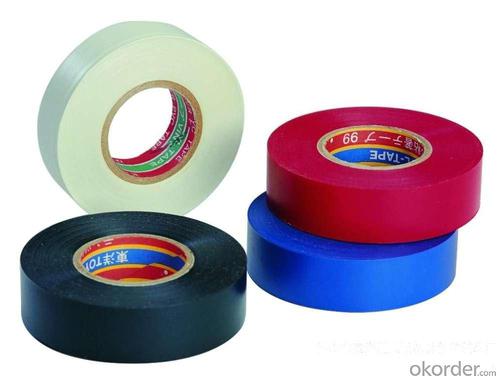
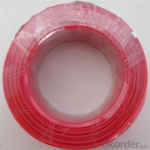
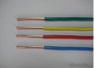
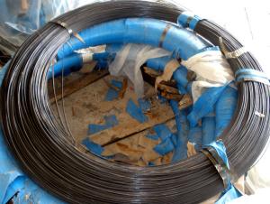
PVC Insulation with High Quality
- Loading Port:
- Guangzhou
- Payment Terms:
- TT OR LC
- Min Order Qty:
- 500 kg
- Supply Capability:
- 300000 kg/month
OKorder Service Pledge
OKorder Financial Service
You Might Also Like
1.Product Description:
Application:
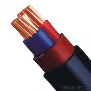
The PVC insulated wire belongs to the series of laying wires, which are mainly suitable for laying at the fixed places. They are widely used as connectors of driving, lighting, electric equipments, instrument and telecommunication equipments with rated voltage to 450/750V.Part of the plastic wires are used at the equipment with AC rated voltage unto 300/500V.and its working temperature is different according to different insulation materials, mainly 70 and 90 degrees temperature, etc.
Category:
According to the conductor type, including solid conductor PVC insulated electrical wire, PVC insulated wire; Flexible PVC insulated wire with different colors.
According to its shape, including flat wire, round wires, etc. with different colors.
Accoding to its core number, including single core wires, multi-core wire, etc. with different colors.
2. Product Characteristic:
Low-smoke zero-halogen characters complying with the requirement of GB/T17650-1998 and GB/T17651-1998
(1)conductivity≤ 10&mμ S/mm
(2)pH≥ 4.3
(3)Smoking density penetration ratio≥ 60%
Low--smoke zero-halogen flame-retardant flexible cable
Flame-retardant properties of the cable can comply with the requirements specified in GB/T 18380.3-2001(IEC60332-3-22: 2000)for category A
Low--smoke zero--halogen fire--resistant flexible cable
Fire-resistant properties of the cable can comply with the requirements specified in GB/T 12666.
3. Product Specification
227 IEC01(BV),BV,BLV | Copper(aluminum) core PVC insulated cable(wire) |
BVV,BLVV | Copper(aluminum) core PVC insulated and sheathed power cable |
277 IEC02(RV),BV | Copper core PVC insulated flexible cable(wire) |
227 IEC05(BV),BV | Copper core PVC insulated cable |
227 IEC06(RV) | Copper core PVC insulated flexible cable |
227 IEC07(BV-90) | Copper core PVC insulated heat-resisting (90°C) cable |
227 IEC08(RV-90) | Copper core PVC insulated heat-resisting (90°C) interconnecting flexible cable |
227 IEC10(BVV),BVV | Copper core PVC insulated and sheathed round cable |
227 IEC42(RVB),RVB | Copper core PVC insulated flat interconnecting flexible cable |
227IEC52(RVV) or 227IEC53(RVV) | Copper core PVC insulated and sheathed round interconnecting flexible cable |
BVR | Copper core PVC insulated flexible cable |
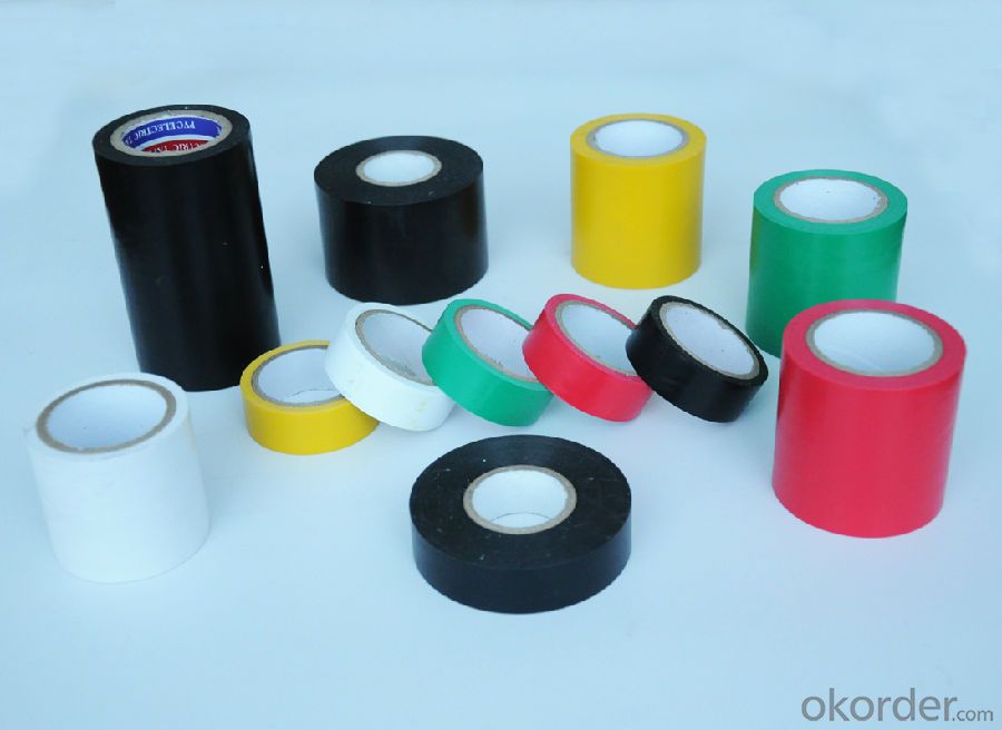
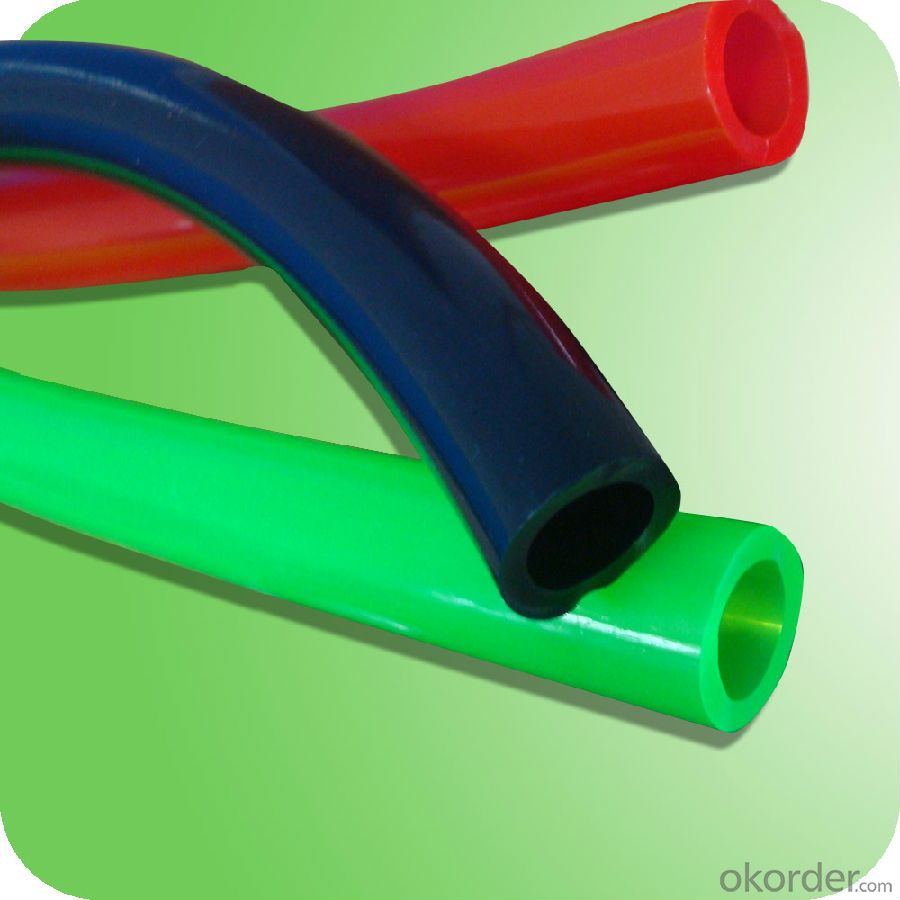
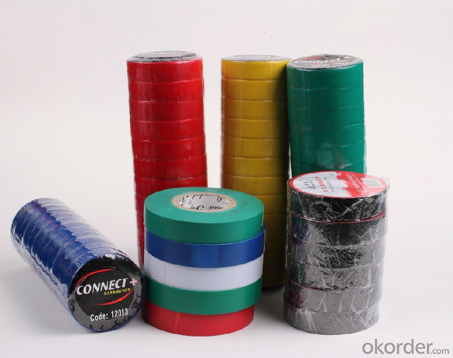
4. Reference Picture
- Q: so im lost in how i should wire my subs. I have two subs that i need to wire both are 2 ohms 400 watts i don't know if i should wire them parallel or series if you can help me out that would be great!
- usually all sub wiring is the same, youll have the rca cables and antenna wire comming from the radio to the amp, power and ground wire going from amp to battery and ground, and than should have 2 wires coming off each sub to the amp, im guessing thatd be parallel, if you wire in series, so like use 2 wires and splice off to each sub, so 2 wires off the amp powering each sub you would up the ohms and put a too much of a load on the amp, people only wire in series when they have too many subs and not enough outlets on the amp, good luck
- Q: I wired an outdoor lamp-post. I tested it before wiring it to the fuse box...and if I touch the lamp-post I feel the current (a slight shock). I will be using a ground fault breaker....so I assume if I wire it to that I am going to loose the connection. Any thoughts on what is wrong?
- In addition to the answer Paul gave, check the wiring that the white wire is the neutral or common wire and that it goes to the shell side of the lamp holder. A few years ago, I had a similar problem, when all of the checks were made, the panel was wired with the black wires on the neutral buss. Hence all of the devices were wired backwards. Call a qualified professional electrician to do the work.
- Q: wiring has ceramic poles
- You need to replace the wiring. Be care-full, if the old wiring has insulation on it, it most likely is asbestos.
- Q: Ceiling lights wire guage
- I think most answerers are thinking you are asking about the size of the wire to the light fixture. Is this what you mean or are you asking about the wiring inside the light fixture?
- Q: I need to wire a single 120v outlet from the 240v volt wire I use on my compressor. Im installing a 120v electric automatic drain valve on my large shop air compressor. The compressor is wired up with SJ00W 10-AWG, 4-wire power cable (red,green,black white wires). and is rated at 240v @ 15-amp(compressor not wire). The drain valve uses a normal house hold current wiring config. (black,white and open copper)The 240v power supply is the only supply I have near by, (two of them actually) Or I would just wire the automatic valve off an outlet and call it a day. So How do I wire a 120v 3-wire set up from the 240v 4-wire supply? Thanks
- If you have 10 AWG wire then you probably have a 30 amp breaker, correct? If so, you can't wire a standard 110v outlet on that large of a breaker. Duplex outlets are only rated for 20 amps. 30 amps and you're into range receptacles. You would probably need to install a sub-panel so you can switch down to a smaller wire size/breaker for the outlet. You could run the red, white and green into the sub-panel as the power source and then install a 15 or 20 amp breaker using 14 or 20 AWG wire to the receptacle respectively.
- Q: the sensor part has 4 wires,(2 white,1 black and 1 red)each light has 1bl.and 1white
- Wiring a Motion Sensor to an Existing Security Light: Materials (5) Wire Nuts (Yellow) Electrical Tape Screwdriver Directions 1. TURN OFF POWER TO FIXTURE! 2. Remove light from base to get to wiring. 3. Remove wire nuts from existing black and white wires. 4. Connect white wires togeather with wire nut. 5. Connect red wire from motion sensor to black wire from lights. 6. Connect black wire from motion sensor to black wire from power source. 7. Replace fixture to base. 8. Turn power back on. Hope this helps.
- Q: It every download on lime-wire basic free and is the down load of lime-wire basic free is lime wire really illegal thanks
- I used lime-wire but it was totally spammed. I got a lot of spyware on my computer, so be very careful. It's basically free but you don't get much for free. It's called file sharing.
- Q: i would like to hook up a cd player in my dakota but i need a wire color diagram, anyboby no where or no the colors
- 1995 Dodge Dakota Wiring Diagram
- Q: what size of wire do i need and is the new fuse box/trip box kept in garage.or where can i get wiring diagrams from
- Lots of wrong answers. Don't take electrical advise from untrained and unqualified people. Is the wire overhead or direct buried? Either way, there are underground rated, direct burial, splice kits made that will splice the wires without the need for a box. They are a set screw terminal aluminum tube with 2 pieces of heat shrink tubing. Buy them at a electrical supply warehouse. One for each conductor. Tell them what you are doing so you get the correct ones. They must be rated for wet locations. So must your wire. I assume you are using a XHHW type wire for direct burial or a THWN for inside buried conduit? Your number 3 copper wire is large enough for 100 amps with no problem at 100 feet. Article 310.16 for the rest of you. You will need to drive a ground rod at the garage and connect it with a number 6 copper wire, and bond the neutral and ground together in the panel the same as in your house. You will need to do this before January 1st when the new national electric code takes effect. In the 2008 code you will need to run a 4 wire feeder to the sub panel in the garage. Your installation will comply with the 2005 National Code. State and local codes may vary. If you need more help, email me.
- Q: a difference of 25 feet with 16 gague wire
- You are not going to notice any difference at all at the length of 25 feet. If you are going to have 100 feet length then I would advice using a 14 gauge wire. It is not going to have any affect on your amp. Only the speaker resistance will have an affect on your power amplifier. Hope this will help you out.
Send your message to us
PVC Insulation with High Quality
- Loading Port:
- Guangzhou
- Payment Terms:
- TT OR LC
- Min Order Qty:
- 500 kg
- Supply Capability:
- 300000 kg/month
OKorder Service Pledge
OKorder Financial Service
Similar products
Hot products
Hot Searches
