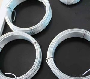
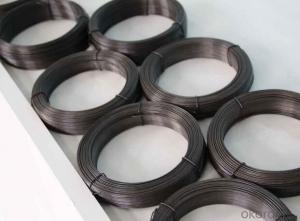
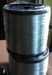
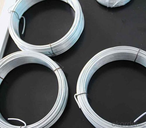
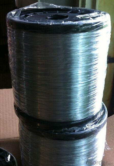
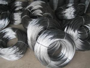
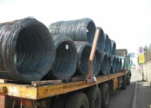
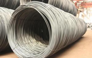
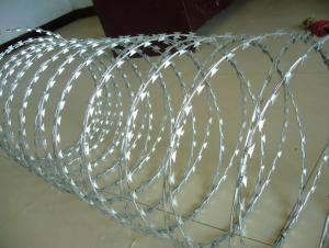
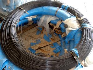
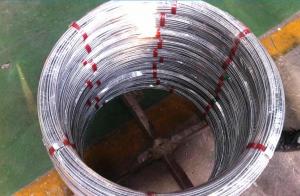
PVC Coated Galvanise Black Annealed Double Loop Tie Wire
- Loading Port:
- Tianjin
- Payment Terms:
- TT OR LC
- Min Order Qty:
- 5 m.t.
- Supply Capability:
- 50000 m.t./month
OKorder Service Pledge
Quality Product, Order Online Tracking, Timely Delivery
OKorder Financial Service
Credit Rating, Credit Services, Credit Purchasing
You Might Also Like
Specification
Material:
Galvanized Iron Wire,Iron Wire
Cross Sectional Shape:
Round
Application:
Construction Wire Mesh
Type:
Galvanized,U Type Wire,Loop Tie Wire
Wild in Width:
1.1M
Surface Treatment:
galvanized
Metal Wire Drawing:
Cold Drawing
Status:
In Hard State
Thickness:
Metal Thick Wire
Galvanized Technique:
Hot Dipped Galvanized,Electro Galvanized
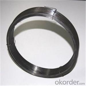
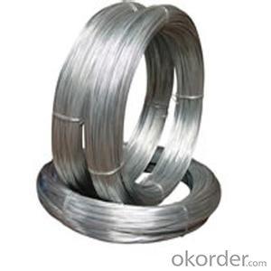
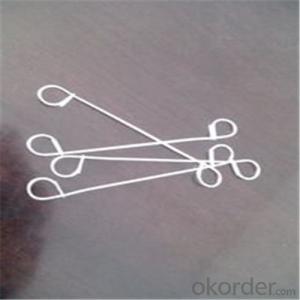
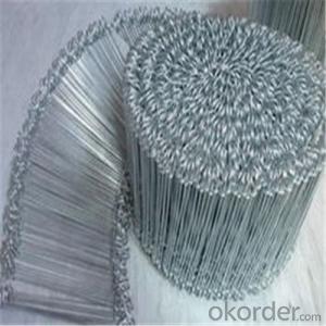
Double Loop Tie Wire
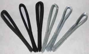
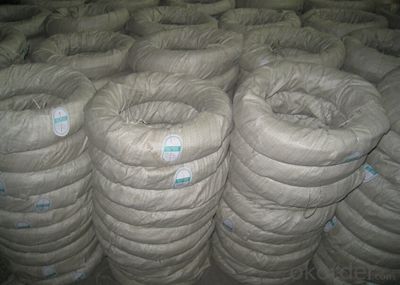
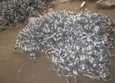
Tie wire is a metal wire product that used to tie bags, Also known as bag tie wire.
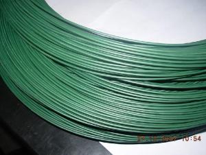
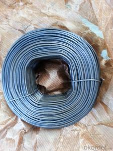
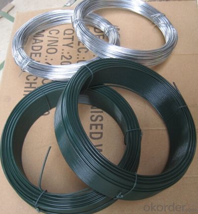
1)Material: black iron wire, galvanized wire , PVC coated wire, stainless steel wire.
2)Wire diameter: 0.5MM-4.0MM.
3)Lenght: 10-25cm.
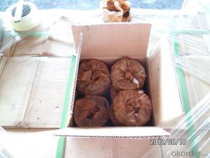
4)Packaging: plastic bags, cardboard boxes, trays, etc. Or according to customer requirement.
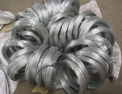
pvc coated loop tie wire for hot sale
We has devoting ourselves to producing and trading for 10 years,eatablishing a good relationship with the company of US,Canada,Mid easten and so on.
Product name | pvc coated loop tie wire for hot sale |
Length | As your request |
| Material | Q195,Q235 |
| Coating | As your demand |
| Weight | 1-800kg/coil |
| Production QTY: | 1000tons/month |
| MOQ: | No |
| Delivery time: | 20days after payment |
| Payment terms: | T/T,L/C |
| Application: | Binding Wire |
| Remarks | No rust |
product size: | (other size as your demands) | |||
| Wire Gauge | SWG in mm | BWG in mm | In Metric System mm | |
| 8# | 4.06 | 4.19 | 4 | |
| 9# | 3.66 | 3.76 | - | |
| 10# | 3.25 | 3.4 | 3.5 | |
| 11# | 2.95 | 3.05 | 3 | |
| 12# | 2.64 | 2.77 | 2.8 | |
| 13# | 2.34 | 2.41 | 2.5 | |
| 14# | 2.03 | 2.11 | - | |
| 15# | 1.83 | 1.83 | 1.8 | |
| 16# | 1.63 | 1.65 | 1.65 | |
| 17# | 1.42 | 1.47 | 1.4 | |
| 18# | 1.22 | 1.25 | 1.2 | |
| 19# | 1.02 | 1.07 | 1 | |
| 20# | 0.91 | 0.89 | 0.9 | |
| 21# | 0.81 | 0.813 | 0.8 | |
| 22# | 0.71 | 0.711 | 0.7 | |
- Q: i have 2 audiobahn 12s and an adiobahn amp in my 2000 malibu...1. the thin blue wire that comes from the amp to the stereo is connected to an orange wire behing the (stock) stero, and when i turn off the car the amp stays on. does anyone know which wire to connect the blue wire to, so the amp turns off with my radio or when i turn off the key.2. only one of my 12s is hitting, i think ther might be a wire connected wrong behind the stero. since i have a stock stereo and i have a converter hooked up, because it had no rca inputs on it. its not the speaker or the rca wire itself, because when i connect it with a y cable to the amp one or the other will work...i would appreciate it if someone could help.
- the present passing during the wires will reason the wires to warmth up if no longer sufficient guage. think of of the masses of thousands of little electrons pushing and shoving back and forth, all this action reasons friction on a molecular point and of course all of us be attentive to friction equals warmth. In an more advantageous guage twine there is extra area for the comparable variety of electons. it relatively is extremely that easy. Use as heavy a guage speaker twine which you would be able to. you will have no sign loss and little warmth.
- Q: has black wires.
- Two black wires in the box would be a hot from the supply and a switched hot to the load. If the timer has only two wires then it should be pretty easy to just connect them. If they are marked line and load then you would have to hook the wire for line to the wire in the box that is always hot from the supply and the other to the wire marked load. If you are still unsure then it really is not a job for you alone, enlist the help of someone with a bit more experience or even an electrician.
- Q: My renter took apart a timer that was hooked to a ceiling fan because the timer was clicking loudly.Now, I just want to simply install a normal on/off switch in it's place. There are two sets of wires coming into the box. One set has a red,white, and black wire coming from it. The other set has just a white and black wire coming into the box. I'm sure this is relatively simple for someone who has wiring expertise. How do I wire a normal light switch to these wires?!?!
- Go okorder under search, type in single pole switch. A short video showing you how to do it will appear.
- Q: The drawing shows two long, straight wires that are suspended from the ceiling. The mass per unit of length of each wire is 0.050kg/m. Each of the four strings suspending the wires has a length of 1.2m. When the wires carry identical currents in opposite directions, the angel between the strings holding the two wires is 15 degrees. What is the current in each wire?? Im not sure what equations to use for this problem.
- Look at it this way a current I2 causes a magnetic field. if a current I1 is in a magnetic field then a force acts on it. F=I1*B*dl where B=I2*(mu0)/(2*pi*d) So the force between those two wires is given by this equation F=I1*I2*(mu0)*dl/(2*pi*d) mu0=4*pi*10power7 d the distance between them In this case I1=I2 dl which shows the lenght of the wire in the magnetic field equals 1 because you do not care about it's lenght from here on it is rather simple I hope
- Q: When I cross the black wire and ground I get a spark. Isnthis normal?
- One you always need a hot wire to operate stuff and to run the circuit. never assume one color wire is the hot wire you never know what someone wired a item or a circuit up with maybe they only had green wire on their truck. I don't care if the wire is red, white, purple, blue , green or black i always to test to see what wires are my hot wires and what wires are line voltage. There are too many people who don't follow code and just wire up stuff how ever they want as long as it works for them. so protect yourself and test everything and wire stuff up right if you don't know how to read a book or get some training like someone else said its not difficult you just have to respect electricity and what it can do.
- Q: Suppose we have a 10v battery.one end of the battery is at 10V electric potential and other is at 0V Hence,the potential difference is 10V.if we measure the voltage( p.d.) across positive terminal at 10V and the middle of the wire connecting both ends of battery will it be less??I mean,at the middle of the wire the electric will not be zero,right??(correct me if am wrong)Thanks!!
- If the wire had some reasonable resistance which prevented melting of the wire and explosion of the battery; the middle of the wire would show half the potential difference between the terminals. The wire connecting the terminals becomes a potentiometer with Voltage falling linearly between the terminals (assuming uniform resistance along the length of the wire). In practice, Voltage drop on a wire supplying power to a load is proportional to the resistance of the wire divided by the resistance of the load. When the wire is the load, all Voltage drop occurs along the wire.
- Q: I Have a 02 Dodge ram with the 5.9L engine and i purchased a O2 simulator because i wanted to remove the cats. what i need to know is which wire is the Signal, 12 volt, and the ground wire on the oxygen sensor. If anyone has any idea please share some info.
- The wires should be color coated. Usually if it is a 4 wire o2 there are two white wires and two black wires and the blacks are both grounds. Same should go with the 2 wire o2 the black is usually the ground and the wite is the 12v wire.
- Q: Hey I have a standard Epiphone Les Paul, and I just bought some brand new Burstbucker pickups online. The one's I bought haven't arrived yet but in the picture, it looks like there is only 1 wire coming out of each pickup. When I take my wire cover off, i can see 1 wire comes out, but it's really 2 wires insulated to look like 1. What can I do so that I can put these expensive pickups in my guitar??
- Are you experienced in this sorta section? i might quite advise that in case you comprehend somebody who can try this sorta stuff no difficulty, ask them to take you thru it step with the aid of step.. although the mixture sounds good although, I fairly like the sound of that..good success and satisfied playing :)
- Q: can you use your existing phone line jacks and wire, then convert the jacks to lan to network computers or printers?
- A LAN wire is wider, and used for VoIP and computer network access. A phone wire is what you use for your telephone, dial-up Internet access, and DSL Internet access.
- Q: subs - dvc 4ohm 2 of them 600wattrms on each wiring it to a 1200 watt amp same brand as sub amp is 1 ohm stable to i wire the subs together and then to the amp a 1ohm? that would give each sub 600 watts right?
- no wat i would do is wire 1 speaker to 1 port and wire the other speaker to the other pot thats if it is a 2 chanel amp... cause if not u will be pulling to much from 1 side and the speakers wont sound right..... u need to turn down the amp to at first and then bring up the bass gradually to make sure the speakers can handle it..... u also have the choice to bride the amp but thats it the spakers can handle the power... all u have to do is hook up positive then negative to 1 speaker the hook up positive then negative to a diffrent speaker but it has to be from a diff channel...... but if ur going to bridge the speakers then u go positive from 1 port to the negative to the negative of the other port this will give u alot more power to ur speakers.... thats why i recomend u hooking them up regular at first........... u also have to make sure ur gornd is like a foot long or less.... the shorter the ground the more the bass
Send your message to us
PVC Coated Galvanise Black Annealed Double Loop Tie Wire
- Loading Port:
- Tianjin
- Payment Terms:
- TT OR LC
- Min Order Qty:
- 5 m.t.
- Supply Capability:
- 50000 m.t./month
OKorder Service Pledge
Quality Product, Order Online Tracking, Timely Delivery
OKorder Financial Service
Credit Rating, Credit Services, Credit Purchasing
Similar products
Hot products
Hot Searches
