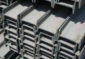
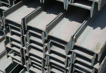
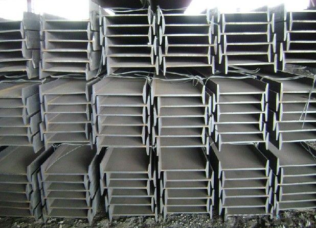
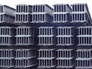
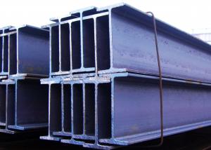
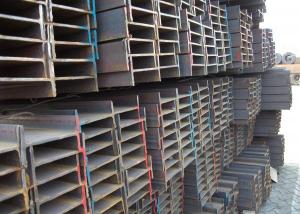
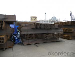
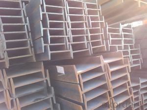
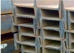
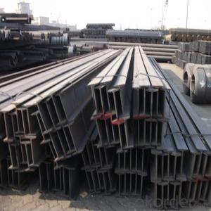
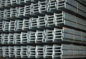
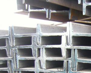
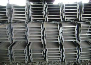
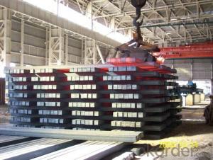
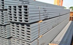
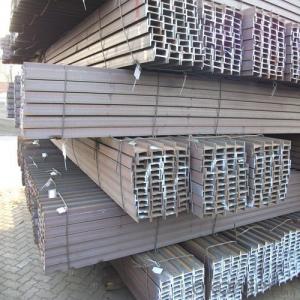
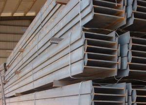
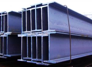
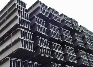
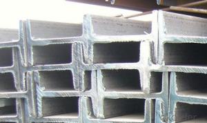
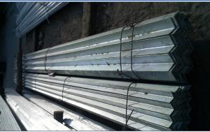
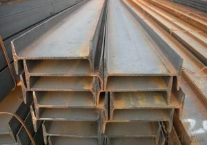
IPEAA Beam High Quality Hot Rolled 80MM-270MM S235JR
- Loading Port:
- Tianjin
- Payment Terms:
- TT or LC
- Min Order Qty:
- 25 m.t.
- Supply Capability:
- 10000 m.t./month
OKorder Service Pledge
OKorder Financial Service
You Might Also Like
Product Applications:
IPEAA Beam High Quality Hot Rolled 80MM-270MM S235JR are ideal for structural applications and are widely used in the construction of buildings and bridges, and the manufacturing, petrochemical, and transportation industries.
Product Advantages:
OKorder'sIPEAA Beam High Quality Hot Rolled 80MM-270MM S235JR are durable, strong, and resist corrosion.
Main Product Features:
· Premium quality
· Prompt delivery & seaworthy packing (30 days after receiving deposit)
· Corrosion resistance
· Can be recycled and reused
· Mill test certification
· Professional Service
· Competitive pricing
Product Specifications:
Manufacture: Hot rolled
Grade: Q195 – 235
Certificates: ISO, SGS, BV, CIQ
Length: 6m – 12m, as per customer request
Packaging: Export packing, nude packing, bundled
Chinese Standard (H*W*T) | Weight (Kg/m) | 6m (pcs/ton) | Light I (H*W*T) | Weight (Kg/m) | 6m (pcs/ton) | Light II (H*W*T) | Weight (Kg/m) | 6M |
100*68*4.5 | 11.261 | 14.8 | 100*66*4.3 | 10.13 | 16.4 | 100*64*4 | 8.45 | 19.7 |
120*74*5.0 | 13.987 | 11.9 | 120*72*4.8 | 12.59 | 13.2 | 120*70*4.5 | 10.49 | 15.8 |
140*80*5.5 | 16.89 | 9.8 | 140*78*5.3 | 15.2 | 10.9 | 140*76*5 | 12.67 | 13.1 |
160*88*6 | 20.513 | 8.1 | 160*86*5.8 | 18.46 | 9 | 160*84*5.5 | 15.38 | 10.8 |
180*94*6.5 | 24.143 | 6.9 | 180*92*6.3 | 21.73 | 7.6 | 180*90*6 | 18.11 | 9.2 |
200*100*7 | 27.929 | 5.9 | 200*98*6.8 | 25.14 | 6.6 | 200*96*6.5 | 20.95 | 7.9 |
220*110*7.5 | 33.07 | 5 | 220*108*7.3 | 29.76 | 5.6 | 220*106*7 | 24.8 | 6.7 |
250*116*8 | 38.105 | 4.3 | 250*114*7.8 | 34.29 | 4.8 | 250*112*7.5 | 28.58 | 5.8 |
280*122*8.5 | 43.492 | 3.8 | 280*120*8.2 | 39.14 | 4.2 | 280*120*8 | 36.97 | 4.5 |
300*126*9 | 48.084 | 3.4 | 300*124*9.2 | 43.28 | 3.8 | 300*124*8.5 | 40.87 | 4 |
320*130*9.5 | 52.717 | 3.1 | 320*127*9.2 | 48.5 | 3.4 | |||
360*136*10 | 60.037 | 2.7 | 360*132*9.5 | 55.23 | 3 |
FAQ:
Q1: Why buy Materials & Equipment from OKorder.com?
A1: All products offered byOKorder.com are carefully selected from China's most reliable manufacturing enterprises. Through its ISO certifications, OKorder.com adheres to the highest standards and a commitment to supply chain safety and customer satisfaction.
Q2: What makes stainless steel stainless?
A2: Stainless steel must contain at least 10.5 % chromium. It is this element that reacts with the oxygen in the air to form a complex chrome-oxide surface layer that is invisible but strong enough to prevent further oxygen from "staining" (rusting) the surface. Higher levels of chromium and the addition of other alloying elements such as nickel and molybdenum enhance this surface layer and improve the corrosion resistance of the stainless material.
Q3: Can stainless steel rust?
A3: Stainless does not "rust" as you think of regular steel rusting with a red oxide on the surface that flakes off. If you see red rust it is probably due to some iron particles that have contaminated the surface of the stainless steel and it is these iron particles that are rusting. Look at the source of the rusting and see if you can remove it from the surface.
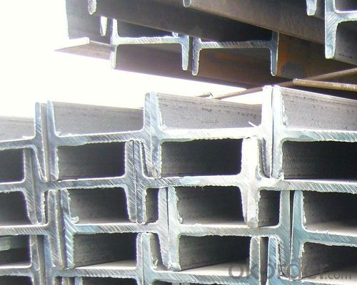
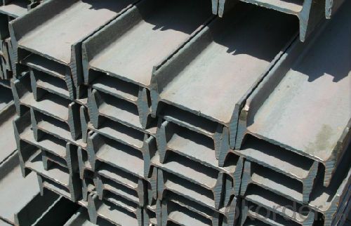
- Q: How do you calculate the moment of inertia for a steel I-beam?
- The moment of inertia for a steel I-beam can be calculated using the formula: I = (1/12) * b * h^3 - (1/12) * (b - 2t) * (h - t)^3, where I represents the moment of inertia, b is the width of the top and bottom flanges, h is the height of the web, and t is the thickness of the flanges and web.
- Q: How do steel I-beams compare to concrete beams in terms of strength?
- In terms of strength, steel I-beams surpass concrete beams. The strength-to-weight ratio of steel is greater than that of concrete, meaning it can bear heavier loads with less material. This is particularly significant in construction, where engineers strive to maximize a building's structural efficiency. Steel I-beams undergo precise manufacturing to meet specific specifications, ensuring consistent strength and load-bearing capacity. They can endure high levels of tension and compression, making them ideal for supporting heavy loads and resisting structural deformations. Additionally, steel possesses excellent ductility, allowing it to bend without breaking, thereby enhancing its overall strength and resilience. On the contrary, concrete beams have their own merits. Although not as strong as steel, concrete exhibits exceptional resistance to fire, making it a popular choice for fireproofing in buildings. Moreover, concrete beams display good resistance to weathering and can withstand harsh environmental conditions better than steel. Nevertheless, when considering strength alone, steel I-beams outshine concrete beams due to their higher strength-to-weight ratio and superior load-bearing capacity.
- Q: What are the different surface finishes available for steel I-beams?
- Steel I-beams can be finished in various ways to serve different purposes and provide distinct advantages. The most prevalent surface finishes for steel I-beams are as follows: 1. Mill Finish: This is the simplest and most common surface finish for steel I-beams. It refers to the untreated surface of the steel beam as it comes straight from the mill. Mill finish is typically characterized by a dull gray appearance and may have minor imperfections or blemishes. It is suitable for applications where neither aesthetics nor corrosion resistance are major concerns. 2. Hot-dip galvanized: To achieve this finish, the steel beam is immersed in a molten zinc bath, forming a protective coating on its surface. Hot-dip galvanizing provides excellent corrosion resistance, as the zinc coating acts as a barrier against moisture and other corrosive elements. Steel I-beams with hot-dip galvanized finishes are commonly employed in outdoor applications or environments where exposure to harsh weather or corrosive substances is expected. 3. Painted: Steel I-beams can also be coated with paint to offer protection against corrosion and enhance their appearance. The paint acts as a protective layer, and painted finishes provide a wide range of color options that can be customized to match specific aesthetic requirements. This finish is often used in architectural and decorative applications where appearance is important. 4. Powder-coated: Powder coating is a dry finishing process in which a powdered coating material is electrostatically applied to the steel beam and then cured under heat. This process results in a durable, smooth, and uniform finish that offers excellent corrosion resistance. Powder-coated steel I-beams are frequently utilized in both indoor and outdoor applications that demand both durability and aesthetics. This finish can also be customized in terms of color and texture. 5. Black oxide: Black oxide is a chemical conversion coating that forms a thin, black oxide layer on the surface of the steel beam. This finish provides mild corrosion resistance while enhancing the beam's appearance with a dark, black color. Black oxide finishes are commonly used in applications where a sleek and uniform appearance is desired, such as architectural or decorative elements. In conclusion, steel I-beams can be finished with mill finish, hot-dip galvanized, painted, powder-coated, or black oxide surfaces. Each finish offers unique advantages in terms of corrosion resistance, aesthetics, and suitability for specific applications. The choice of surface finish depends on factors such as the intended use, environmental conditions, and desired appearance.
- Q: Can steel I-beams be used for railway or bridge construction?
- Certainly, railway or bridge construction can utilize steel I-beams. Their utilization in such applications is commonplace owing to their robustness and endurance. These beams possess the capability to bear substantial loads and furnish the essential structural integrity that railway tracks and bridges necessitate. Moreover, steel I-beams exhibit resistance to corrosion, rendering them suitable for enduring outdoor conditions. Furthermore, their adaptability permits the implementation of diverse designs and configurations tailored to meet specific engineering prerequisites. In summary, steel I-beams consistently prove to be a prevalent and dependable option for railway and bridge construction endeavors.
- Q: How are steel I-beams sized and classified?
- Steel I-beams are sized and classified based on their dimensions, particularly their depth, width, and weight per foot. The size and classification of steel I-beams are determined by industry standards and specifications, such as the American Institute of Steel Construction (AISC) standards. These standards ensure that I-beams are designed and manufactured to support specific loads and structural requirements.
- Q: Are there any health or safety concerns associated with steel I-beams?
- Health and safety concerns can indeed arise in relation to steel I-beams. Here, we provide several examples: 1. Installation Hazards: When installing steel I-beams, there exists a risk of accidents or injuries due to their weight and size. To prevent such accidents, it is essential to adhere to appropriate lifting techniques and safety precautions. 2. Structural Integrity: Inadequate design, manufacturing, or installation of steel I-beams can result in structural failure. This failure can lead to collapses or accidents, posing significant safety hazards to building occupants or workers. 3. Fire Resistance: Steel I-beams are vulnerable to heat and can lose their strength when exposed to high temperatures. In the event of a fire, this compromises the structural integrity of the building, potentially endangering the lives of those inside. 4. Corrosion: Insufficient protection against corrosion can cause steel I-beams to deteriorate over time. Corroded beams may lose their strength, posing safety risks to the structure. Regular maintenance and inspection are crucial for identifying and addressing signs of corrosion. 5. Noise and Vibration: Steel I-beams have the ability to transmit noise and vibrations throughout a structure, particularly in buildings with heavy machinery or equipment. Prolonged exposure to excessive noise and vibrations can have adverse effects on human health, such as hearing loss or musculoskeletal disorders. To mitigate any potential health or safety concerns, it is imperative to prioritize safety measures and seek guidance from professionals like structural engineers and construction experts. They can ensure that steel I-beams are correctly installed and maintained, thereby minimizing risks.
- Q: How do you calculate the deflection of steel I-beams?
- To calculate the deflection of steel I-beams, you can use the Euler-Bernoulli beam theory or more advanced structural analysis methods such as finite element analysis (FEA). The Euler-Bernoulli beam theory involves applying the formula for deflection based on the applied load, beam properties (such as moment of inertia and modulus of elasticity), and the beam's length. FEA, on the other hand, utilizes computer simulations to determine the deflection by discretizing the beam into smaller elements and solving the structural equations numerically.
- Q: How do steel I-beams contribute to the overall sustainability of a building?
- There are several ways in which the overall sustainability of a building is enhanced by the presence of steel I-beams. To begin with, the utilization of steel as a construction material offers exceptional durability and longevity. This implies that I-beams crafted from steel can endure heavy loads and provide structural support for an extended period. Consequently, the need for frequent repairs or replacements is minimized, resulting in a reduction of waste and conservation of resources. Additionally, steel is a recyclable material, allowing for the production of I-beams using recycled steel or the recycling of the beams themselves upon reaching the end of their lifespan. This recycling process significantly diminishes the environmental impact associated with steel production and contributes to the preservation of natural resources. Moreover, the energy required for steel recycling is considerably lower than that needed for its initial production, further bolstering sustainability efforts. Furthermore, steel I-beams possess a high strength-to-weight ratio, meaning they can support substantial loads while utilizing a relatively smaller quantity of material compared to alternative options. This material efficiency reduces the carbon footprint of a building overall, as less steel is necessary for the construction of the structure. Another facet of sustainability enhanced by steel I-beams is the ability to create open and flexible floor plans. The incorporation of I-beams allows for longer spans and wider spaces, minimizing the necessity for additional columns or supports. This design flexibility permits adaptable and customizable spaces that can accommodate changing needs over time, ultimately prolonging the lifespan of a building and reducing the potential for demolition and waste. In conclusion, the presence of steel I-beams contributes significantly to the overall sustainability of a building through their durability, recyclability, efficient material usage, and design flexibility. Architects and builders who choose steel I-beams can actively participate in the creation of environmentally-friendly structures that conserve resources, minimize waste, and have an extended lifespan.
- Q: Are steel I-beams fire-resistant?
- Steel I-beams are not inherently fire-resistant. However, they have a high melting point which allows them to withstand fire for a longer duration compared to other building materials like wood. To enhance their fire resistance, steel I-beams are often coated with fire-resistant materials or encased in fire-rated materials such as concrete or gypsum to provide additional protection against fire.
- Q: Can steel I-beams be used in retail or commercial building renovation projects?
- Yes, steel I-beams can be used in retail or commercial building renovation projects. Steel I-beams are commonly used in construction due to their strength and durability, making them suitable for supporting heavy loads and providing structural stability. Whether it's for creating open floor plans, adding additional floors, or reinforcing existing structures, steel I-beams are a popular choice in commercial and retail building renovations.
Send your message to us
IPEAA Beam High Quality Hot Rolled 80MM-270MM S235JR
- Loading Port:
- Tianjin
- Payment Terms:
- TT or LC
- Min Order Qty:
- 25 m.t.
- Supply Capability:
- 10000 m.t./month
OKorder Service Pledge
OKorder Financial Service
Similar products
Hot products
Hot Searches
Related keywords
