


hot rolled high quality IPE IPEAA GB Q235 S235JR
- Ref Price:
-

- Loading Port:
- Shanghai
- Payment Terms:
- TT OR LC
- Min Order Qty:
- 25 m.t.
- Supply Capability:
- 60000 m.t./month
OKorder Service Pledge
OKorder Financial Service
You Might Also Like
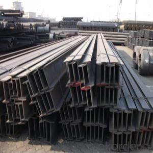
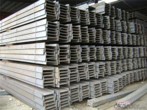
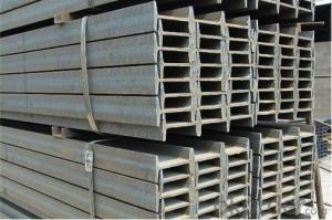
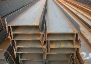
IPE Details:
| Minimum Order Quantity: | Unit: | m.t. | Loading Port: | ||
| Supply Ability: | Payment Terms: | Package: | wire rod bundle |
Product Description:
Product Description:
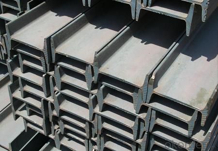
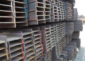
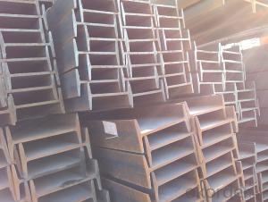
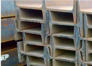
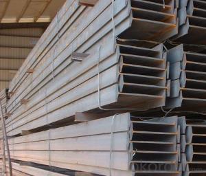
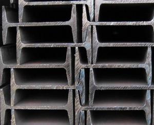
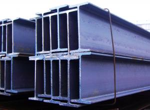
Specifications of IPE Beam
1. Invoicing on theoretical weight or actual weight as customer request
2. Standard: EN10025, GB Standard, ASTM
3. Grade: Q235B, Q345B, SS400, ASTM A36, S235JR, S275JR
4. Length: 5.8M, 6M, 9M, 12M as following table
5. Sizes: 80mm-270mm
Dimensions(mm) | |||||
h | b | s | t | Mass Kg/m | |
IPE80 | 80 | 46 | 3.80 | 5.20 | 6.00 |
IPE100 | 100 | 55 | 4.10 | 5.70 | 8.10 |
IPE120 | 120 | 64 | 4.80 | 6.30 | 10.40 |
IPE140 | 140 | 73 | 4.70 | 6.90 | 12.90 |
IPE160 | 160 | 82 | 5.00 | 7.40 | 15.80 |
IPE180 | 180 | 91 | 5.30 | 8.00 | 18.80 |
IPE200 | 200 | 100 | 5.60 | 8.50 | 22.40 |
IPE220 | 220 | 110 | 5.90 | 9.20 | 26.20 |
IPE240 | 240 | 120 | 6.20 | 9.80 | 30.70 |
IPE270 | 270 | 135 | 6.60 | 10.20 | 36.10 |
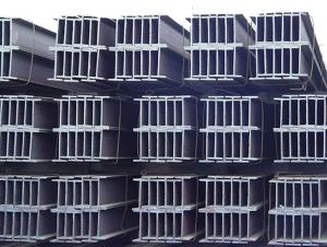
Appications of IPE Beam
1. Supporting members, most commonly in the house raising industry to strengthen timber bears under houses. Transmission line towers, etc
2. Prefabricated structure
3. Medium scale bridges
4. It is widely used in various building structures and engineering structures such as roof beams, bridges, transmission towers, hoisting machinery and transport machinery, ships, industrial furnaces, reaction tower, container frame and warehouse etc.
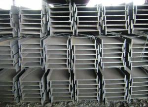
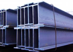
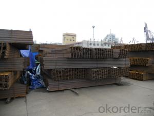
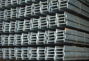
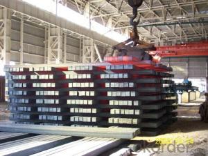
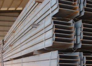
Package & Delivery of IPE Beam
1. Packing: it is nude packed in bundles by steel wire rod
2. Bundle weight: not more than 3.5MT for bulk vessel; less than 3 MT for container load
3. Marks: Color marking: There will be color marking on both end of the bundle for the cargo delivered by bulk vessel. That makes it easily to distinguish at the destination port.
4. Tag mark: there will be tag mark tied up on the bundles. The information usually including supplier logo and name, product name, made in China, shipping marks and other information request by the customer.
If loading by container the marking is not needed, but we will prepare it as customer request.
5. Transportation: the goods are delivered by truck from mill to loading port, the maximum quantity can be loaded is around 40MTs by each truck. If the order quantity cannot reach the full truck loaded, the transportation cost per ton will be little higher than full load.
6. Delivery of IPE Beam: 30 days after getting L/C Original at sight or T/T in advance
Production flow of IPE Beam
Material prepare (billet) —heat up—rough rolling—precision rolling—cooling—packing—storage and transportation
- Q: What are the different types of steel I-beam connections for cantilever structures?
- For cantilever structures, there are various types of steel I-beam connections that are commonly used, each offering distinct benefits and suitability for specific applications. Some of the frequently utilized connections are as follows: 1. Welded Connection: The most common and straightforward method is to directly weld the end of the beam to the supporting structure. This provides exceptional rigidity and strength. However, skilled welding professionals are required, and residual stresses may occur. 2. Bolted Connection: This connection involves securing steel plates with holes to the ends of the I-beams using bolts, which are then fastened to the supporting structure. Bolted connections offer easy installation, adjustability, and the option to disassemble and reuse the structure if necessary. However, they may have some flexibility and require regular inspection and bolt tightening. 3. Cleat Connection: A cleat connection entails welding a steel plate with holes to the end of the I-beam, which is then bolted to the supporting structure. This connection combines the advantages of both welding and bolting, providing high strength and adjustability. Cleat connections are commonly employed in large cantilever structures due to their robustness and versatility. 4. Moment Connection: This type of connection is specifically designed to transfer bending moments between the I-beam and the supporting structure. Moment connections often involve welding stiffeners or plates to the flanges and web of the beam, creating a rigid joint. These connections are ideal for structures subjected to substantial loads and moments, such as bridges or heavy industrial applications. 5. Shear Connection: Shear connections primarily transfer vertical loads between the I-beam and the supporting structure. These connections typically involve welding or bolting steel plates to the flanges and webs of the beam, providing excellent load-bearing capacity. Shear connections are commonly utilized in cantilever structures where heavy vertical loads need to be supported. When selecting the appropriate steel I-beam connection for a cantilever structure, it is crucial to consider the specific requirements and load conditions. Consulting with a structural engineer or experienced professional is highly recommended to ensure the optimal connection method is chosen for the specific application.
- Q: Can steel I-beams be used in airport terminals?
- Indeed, airport terminals can utilize steel I-beams effectively. The construction industry frequently employs steel I-beams due to their robustness, longevity, and adaptability. They serve as a crucial structural support system, often employed to establish the framework for expansive, unobstructed areas like airport terminals. The remarkable load-bearing capacity of steel I-beams permits the creation of vast spans and spacious floor plans, which are indispensable in airport terminals. These features enable the accommodation of sizable crowds and provide flexibility for various amenities such as check-in counters, security zones, lounges, and retail spaces. Furthermore, steel I-beams possess the ability to endure harsh weather conditions and possess fire-resistant properties, rendering them an ideal choice for airport terminals that prioritize safety and security.
- Q: What is the maximum load capacity of a steel I-beam?
- The maximum load capacity of a steel I-beam can vary depending on various factors such as the dimensions of the beam, the type of steel used, and the specific application. It is essential to consult engineering specifications, load charts, and professional guidance to determine the precise maximum load capacity for a particular steel I-beam.
- Q: What are the different types of steel I-beam connections for staircases?
- There are several types of steel I-beam connections commonly used in staircases. These connections are crucial for ensuring the stability and strength of the staircase structure. Here are some of the different types: 1. Welded Connection: This is the most common type of connection used in steel staircases. It involves welding the I-beam to the stringers or other supporting members. Welding provides a strong and durable connection, ensuring the stability of the staircase. 2. Bolted Connection: In this type of connection, the I-beam is bolted to the stringers or other supporting members using high-strength bolts. Bolted connections are convenient as they allow for easy disassembly and reassembly if required. However, they may not be as strong as welded connections. 3. Cleat Connection: A cleat is a steel plate that is bolted to the underside of the I-beam and attached to the stringers or other supporting members. This connection provides additional support and stability to the staircase. 4. Plate Connection: This type of connection involves using steel plates to connect the I-beam to the stringers or other supporting members. The plates are typically welded or bolted to both the I-beam and the supporting members, ensuring a secure connection. 5. Beam-Column Connection: In some staircases, the I-beam may need to be connected to a vertical column for added support. This connection is typically achieved through welding or bolting, depending on the specific design requirements. It is important to note that the choice of steel I-beam connection for a staircase depends on various factors such as the load-bearing capacity, design requirements, and construction methods. Consulting with a structural engineer or a professional staircase designer is recommended to ensure the appropriate connection type is selected to meet the specific needs of the staircase project.
- Q: Can steel I-beams be used for mining facilities?
- Yes, steel I-beams can be used for mining facilities due to their strength, durability, and load-bearing capabilities. They provide structural support and can withstand heavy loads, making them suitable for various applications in mining facilities such as supporting roofs, reinforcing tunnels, or constructing sturdy equipment platforms.
- Q: Can steel I-beams be used for warehouses?
- Indeed, warehouses can utilize steel I-beams. Steel I-beams are frequently employed as structural supports in diverse construction endeavors, such as warehouses. Their renown stems from their robustness, resilience, and capacity to endure substantial burdens. Steel I-beams are exceptional in ensuring structural integrity and spanning considerable distances, thereby proving to be ideal for constructing warehouses that necessitate extensive unobstructed areas. Furthermore, customizing and fabricating steel I-beams to align with the precise demands of the warehouse design is effortless. All in all, given their dependability and cost-effectiveness, steel I-beams are a favored alternative for warehouses.
- Q: What are the typical spans achievable with steel I-beams?
- The achievable spans of steel I-beams can vary depending on several factors, including the size and shape of the beam, the load it must support, and the design specifications of the structure in which it is utilized. Steel I-beams are renowned for their strength and ability to bear weight, making them a favored option for various construction endeavors. Generally speaking, steel I-beams can achieve spans that range from a few feet to several hundred feet. For smaller residential or commercial projects, spans of 20-30 feet are commonly seen. In larger commercial or industrial buildings, steel I-beams can achieve spans of 40-60 feet or more. Nevertheless, it is important to recognize that these are merely typical spans and not absolute limitations. By employing proper engineering and design considerations, steel I-beams can be utilized to achieve even longer spans. Adjustments to factors such as the beam's depth, flange width, and thickness can enhance its load-bearing capacity and extend its span capabilities. Ultimately, the attainable spans of steel I-beams are contingent upon the specific requirements and limitations of a particular project. Seeking guidance from a structural engineer or a professional in the realm of steel construction is essential in determining the appropriate beam size and span for a given application.
- Q: How are steel I-beams used in floor framing?
- Steel I-beams are commonly used in floor framing to provide structural support and distribute the weight of the building evenly across large spans. These beams are placed horizontally and serve as the primary load-bearing members, allowing for open floor plans and eliminating the need for interior load-bearing walls.
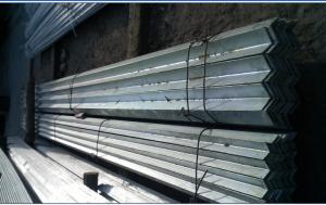
- Q: What are the different types of steel surface treatments available for I-beams?
- There are several types of steel surface treatments available for I-beams, including galvanizing, painting, powder coating, and shot blasting. Each treatment offers unique advantages and can be chosen based on specific requirements such as corrosion resistance, aesthetic appeal, or durability.
- Q: How do steel I-beams contribute to the overall sustainability of a renovation project?
- There are several ways in which a renovation project benefits from the inclusion of steel I-beams, ultimately enhancing overall sustainability. To begin with, steel is an incredibly eco-friendly material for construction. It stands out as one of the most environmentally conscious options available due to its high recyclability. In fact, manufacturing steel from recycled sources consumes notably less energy compared to producing it from raw materials. By incorporating steel I-beams into a renovation project, the demand for new steel production is reduced, resulting in a minimized carbon footprint. Moreover, steel I-beams provide exceptional strength and durability, allowing for efficient structural designs. As a result, fewer materials are necessary to support the load, leading to reduced overall material consumption. The utilization of steel I-beams thus enables a renovation project to achieve the desired structural integrity while minimizing material waste. Additionally, steel is renowned for its longevity and resistance to deterioration. Properly maintained steel I-beams have an extremely low risk of rotting, warping, or being attacked by pests, which are common issues encountered in renovation projects involving alternative materials like wood. This longevity ensures that the renovation will have a lasting impact, diminishing the need for future repairs or replacements. Lastly, steel I-beams offer flexibility in both design and construction. Their lightweight nature facilitates easier transportation and installation, ultimately reducing energy consumption throughout the construction process. Furthermore, steel structures can be easily modified or expanded in the future, providing adaptability to changing needs and minimizing the necessity for additional construction. In conclusion, the inclusion of steel I-beams significantly contributes to the overall sustainability of a renovation project. Their recyclability, strength, durability, and flexibility all play pivotal roles in reducing environmental impact, minimizing waste, and ensuring long-term sustainability.
Send your message to us
hot rolled high quality IPE IPEAA GB Q235 S235JR
- Ref Price:
-
- Loading Port:
- Shanghai
- Payment Terms:
- TT OR LC
- Min Order Qty:
- 25 m.t.
- Supply Capability:
- 60000 m.t./month
OKorder Service Pledge
OKorder Financial Service
Similar products

Hot products

Hot Searches
Related keywords

