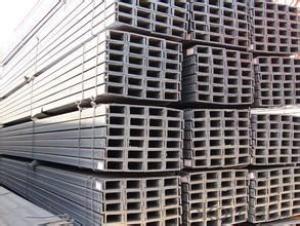
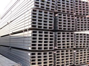
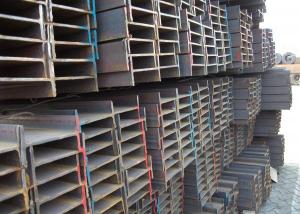
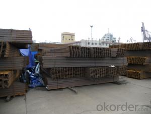
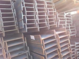
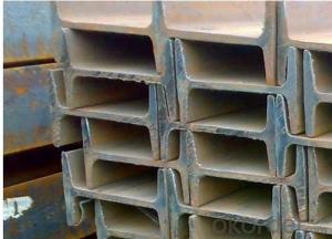
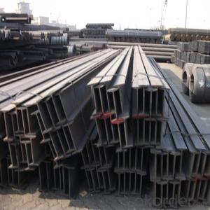
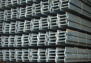
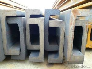
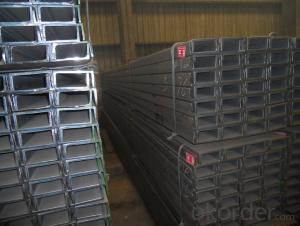
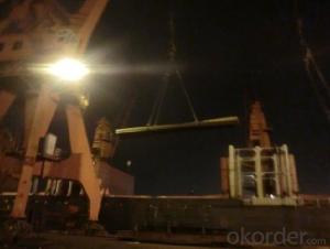
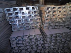
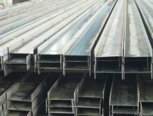
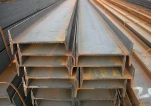
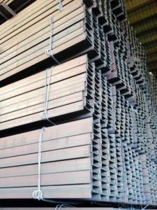
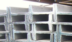
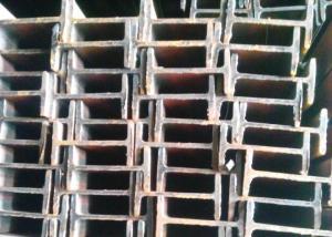
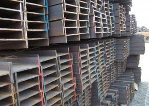
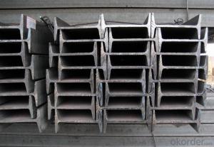
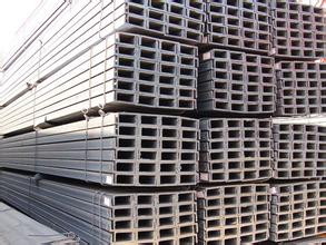
Hot Rolled Mild Carbon Structural Steel U-Channel
- Loading Port:
- Qingdao
- Payment Terms:
- TT or LC
- Min Order Qty:
- 2000 PCS
- Supply Capability:
- 40000 PCS/month
OKorder Service Pledge
OKorder Financial Service
You Might Also Like
Hot Rolled Mild Carbon Structural Steel U-Channel
OKorder is offering high quality Hot Rolled Mild Carbon Structural Steel U-Channels at great prices with worldwide shipping. Our supplier is a world-class manufacturer of steel, with our products utilized the world over. OKorder annually supplies products to European, North American and Asian markets. We provide quotations within 24 hours of receiving an inquiry and guarantee competitive prices.
Product Applications:
Hot Rolled Mild Carbon Structural Steel U-Channels are ideal for structural applications and general fabricating.
Product Advantages:
OKorder's Steel Channels are durable, strong, and resists corrosion.
Main Product Features:
· Premium quality
· Prompt delivery & seaworthy packing (7-10 days after receiving deposit)
· Corrosion resistance
· Can be recycled and reused
· Mill test certification
· Professional Service
· Competitive pricing
Product Specifications:
Base Model
Grade: Q195 / Q235 / Q215 / Q345 / SS400 / S235JR, A36, SS400, SS540, ASTM A36
Height: 50 – 400mm
Thickness: 4.5 – 14.5mm
Length: As per customer request
Max Dimensions: 50*37*4.5mm – 400*104*14.5mm
Surface: Painted, galvanized, as per customer request
Punch: Punched as per customer request
Light Model
Grade: Q195 / Q235 / Q215 / Q345 / SS400 / S235JR, A36, SS400, SS540, ASTM A36
Height: 50 – 400mm
Thickness: 4.4 – 8.0mm
Length: As per customer request
Max Dimensions: 50*32*4.4mm – 400*115*8.0mm
Surface: Painted, galvanized, as per customer request
Punch: Punched as per customer request
FAQ:
Q1: Why buy Materials & Equipment from OKorder.com?
A1: All products offered byOKorder.com are carefully selected from China's most reliable manufacturing enterprises. Through its ISO certifications, OKorder.com adheres to the highest standards and a commitment to supply chain safety and customer satisfaction.
Q2: How do we guarantee the quality of our products?
A2: We have established an advanced quality management system which conducts strict quality tests at every step, from raw materials to the final product. At the same time, we provide extensive follow-up service assurances as required.
Q3: How soon can we receive the product after purchase?
A3: Within three days of placing an order, we will begin production. The specific shipping date is dependent upon international and government factors, but is typically 7 to 10 workdays.
Q4: What makes stainless steel stainless?
A4: Stainless steel must contain at least 10.5 % chromium. It is this element that reacts with the oxygen in the air to form a complex chrome-oxide surface layer that is invisible but strong enough to prevent further oxygen from "staining" (rusting) the surface. Higher levels of chromium and the addition of other alloying elements such as nickel and molybdenum enhance this surface layer and improve the corrosion resistance of the stainless material.
Q5: Can stainless steel rust?
A5: Stainless does not "rust" as you think of regular steel rusting with a red oxide on the surface that flakes off. If you see red rust it is probably due to some iron particles that have contaminated the surface of the stainless steel and it is these iron particles that are rusting. Look at the source of the rusting and see if you can remove it from the surface.
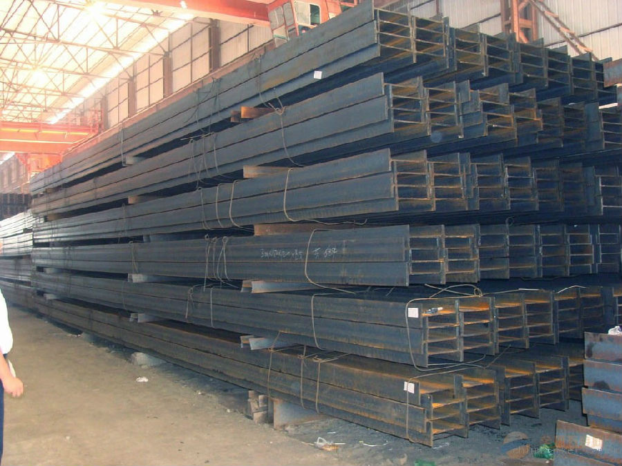
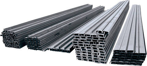
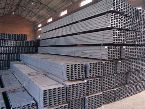
Images:
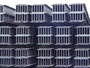
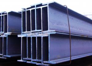
- Q: What are the different types of loads that steel I-beams can withstand?
- Steel I-beams are commonly used in construction and engineering projects due to their high strength and load-bearing capabilities. These beams can withstand various types of loads, including: 1. Dead Loads: These are the permanent loads that are always present on the structure, such as the weight of the building materials, fixtures, and equipment. Steel I-beams are designed to carry dead loads without deforming or collapsing. 2. Live Loads: Also known as dynamic loads, these are temporary or moving loads that can change in magnitude and position. Examples include the weight of people, furniture, vehicles, and equipment. Steel I-beams are designed to resist the stresses caused by these live loads and distribute the weight effectively to prevent structural failure. 3. Wind Loads: Buildings and structures are subjected to wind forces that exert pressure on their surfaces. Steel I-beams are designed to withstand wind loads by offering resistance to lateral forces and minimizing deflection. The specific wind load capacity of an I-beam depends on factors such as the shape and orientation of the structure, local wind speed, and building codes. 4. Snow Loads: In regions that experience heavy snowfall, the weight of accumulated snow on roofs and other horizontal surfaces can create significant loads. Steel I-beams are engineered to handle these snow loads by providing sufficient strength and stiffness to support the weight without excessive deflection or failure. 5. Seismic Loads: Earthquakes generate forces that can cause severe damage to structures. Steel I-beams are designed to resist these seismic loads by incorporating ductility and flexibility into their design. They can absorb and distribute the seismic forces, preventing catastrophic failures and ensuring the safety of the structure. It is important to note that the load-bearing capacity of steel I-beams depends on various factors, including the material properties, beam dimensions, and the structural design. Proper engineering analysis and calculations are essential to determine the specific load limits for a given application.
- Q: What are the typical lengths of steel I-beams?
- The specific application and manufacturer can cause variations in the typical lengths of steel I-beams. Steel I-beams commonly range from 20 feet to 40 feet in length, making them frequently employed in construction projects to ensure stability and structural integrity. Moreover, certain manufacturers may provide tailor-made lengths to fulfill project requirements. To ascertain the suitable length of steel I-beams for a particular application, it is crucial to consult with engineers and architects.
- Q: What are the common connections details for steel I-beams?
- The connection details for steel I-beams can vary depending on the specific application and design requirements. However, structural steel construction commonly employs several connection methods. One method frequently used is the welded connection, where the flanges and web of the I-beam are welded to the supporting structure, such as columns or beams. Welded connections offer exceptional strength and rigidity, making them suitable for heavy-duty applications with high loads. Another method is the bolted connection, where bolts are utilized to connect the I-beam to the supporting structure. Bolted connections provide flexibility during installation and allow for easy disassembly if necessary. They are often employed in applications that foresee adjustability or future modifications. Furthermore, there exist hybrid connection methods that combine both welding and bolting. These connections strike a balance between the strength and rigidity of welded connections and the flexibility of bolted connections. Hybrid connections are commonly chosen when specific design requirements call for a combination of these characteristics. It is crucial to emphasize that the specific connection details for steel I-beams must adhere to local building codes and industry standards. Structural engineers and design professionals typically determine the appropriate connection method based on factors such as load requirements, structural stability, and construction feasibility.
- Q: Can steel I-beams be used in airport terminal construction?
- Yes, steel I-beams can be used in airport terminal construction. Steel I-beams are commonly used in the construction industry due to their strength, durability, and ability to support heavy loads. In airport terminal construction, where large open spaces and long spans are often required, steel I-beams are often the preferred choice for structural framing. They provide the necessary structural integrity and flexibility to accommodate the complex design and functional requirements of modern airport terminals.
- Q: Can Steel I-Beams be used for theater stage construction?
- Yes, steel I-beams can be used for theater stage construction. Steel I-beams are commonly used in construction due to their strength, durability, and load-bearing capabilities. Their structural integrity makes them ideal for supporting heavy loads, such as stage equipment, lighting rigs, and scenic elements. Additionally, steel I-beams offer versatility in design as they can be easily modified, welded, or bolted together to create various stage configurations. They also provide stability and safety, minimizing the risk of structural failure during performances. Overall, steel I-beams are a popular choice for theater stage construction due to their strength, reliability, and ability to handle the demanding requirements of theatrical productions.
- Q: How do steel I-beams distribute loads?
- Steel I-beams distribute loads by transferring the weight or force applied to them to the vertical support columns or walls on either end of the beam. The flanges (horizontal top and bottom sections) of the I-beam resist bending, while the web (vertical middle section) resists shear stress. This design allows the I-beam to efficiently distribute and transfer loads along its length, making it a common choice for structural support in buildings and bridges.
- Q: Can steel I-beams be used for food processing plants?
- Yes, steel I-beams can be used for food processing plants. Steel I-beams are commonly used in construction for their strength, durability, and load-bearing capabilities. These properties make them suitable for supporting heavy equipment, machinery, and structures in food processing plants. Additionally, steel I-beams are resistant to corrosion, which is important in environments where food safety and hygiene are paramount. They can also be easily cleaned and maintained, ensuring a safe and sanitary processing environment. Overall, steel I-beams are a popular choice in the construction of food processing plants due to their strength, durability, and suitability for the specific requirements of the industry.
- Q: Are there any health and safety considerations when working with steel I-beams?
- Yes, there are several health and safety considerations when working with steel I-beams. Some of these include the risk of falling objects or materials, the need for proper lifting techniques and equipment to prevent strain or injuries, the importance of wearing appropriate personal protective equipment (PPE) such as gloves, safety glasses, and steel-toed boots, and the need for proper training and supervision to ensure safe handling and installation of the I-beams. Additionally, workers should be aware of potential hazards such as sharp edges, hot surfaces, and the risk of electrical shock if working near power lines or electrical equipment. Regular inspections and maintenance of the I-beams and surrounding work areas are also crucial to ensure ongoing safety.
- Q: Can steel I-beams be used for underground structures?
- Indeed, underground structures can make use of steel I-beams. Steel, a highly versatile and durable material, is capable of enduring various environmental conditions, even when buried underground. The construction industry often relies on steel I-beams due to their strength and ability to bear heavy loads, making them suitable for a wide range of applications, including underground structures. To employ steel I-beams for underground structures, several factors must be taken into account. Firstly, it is necessary to properly treat and coat the steel beams to safeguard them against corrosion caused by moisture and soil chemicals. This can be achieved through techniques such as galvanization or the application of epoxy coatings. Additionally, the implementation of effective drainage systems is crucial to prevent water accumulation, which could expedite corrosion. Steel I-beams find utility in various underground structures, such as basements, tunnels, underground parking lots, and even mining operations. Their capacity for structural support and ability to withstand heavy loads make them an appropriate choice for these applications. Furthermore, steel beams can be easily fabricated and customized to meet specific design requirements, allowing for flexibility in the creation of underground structures. It is important to highlight that expertise in engineering and meticulous planning are vital when employing steel I-beams for underground structures. Factors such as soil conditions, water table levels, and the overall design and purpose of the structure must be taken into consideration to ensure the safety and durability of the underground construction. It is highly recommended to consult with experienced structural engineers and architects specializing in underground construction to guarantee the proper and secure utilization of steel I-beams in these contexts.
- Q: What are the different methods of joining steel I-beams together?
- There are several methods of joining steel I-beams together, depending on the specific requirements of the structure and the desired strength and durability of the joint. Some common methods include: 1. Welding: Welding is one of the most commonly used methods for joining steel I-beams together. It involves melting and fusing the edges of the beams using heat, creating a strong and permanent bond. Different types of welding techniques, such as arc welding or MIG welding, can be employed depending on the specific application. 2. Bolted connections: Bolted connections involve using high-strength bolts to connect the beams together. Holes are drilled in the flanges and webs of the beams, and bolts are inserted and tightened to create a secure connection. This method allows for easy disassembly and modification of the structure if required. 3. Riveting: Riveting is an older method of joining steel beams, but it can still be used for specific applications. It involves inserting a metal rivet through pre-drilled holes in the beams and then hammering or compressing the rivet to create a permanent connection. Riveted joints are often used in historical or architectural structures for aesthetic purposes. 4. Adhesive bonding: Adhesive bonding involves using high-strength adhesives or epoxy resins to bond the surfaces of the steel beams together. This method is often used in situations where welding or bolting is not possible or desirable. Adhesive bonding can provide a strong and durable joint, but it may not be suitable for high-stress applications. 5. Mechanical fasteners: Mechanical fasteners, such as steel plates or brackets, can be used to join steel I-beams together. These fasteners are typically bolted or welded to the beams, providing additional strength and stability to the joint. Mechanical fasteners are often used in conjunction with other joining methods to enhance the structural integrity of the connection. It is important to consider factors such as the load-bearing capacity, structural integrity, and ease of installation and maintenance when selecting the most appropriate method for joining steel I-beams together. Consulting with a structural engineer or a professional in the field can help determine the best joining method for a specific application.
Send your message to us
Hot Rolled Mild Carbon Structural Steel U-Channel
- Loading Port:
- Qingdao
- Payment Terms:
- TT or LC
- Min Order Qty:
- 2000 PCS
- Supply Capability:
- 40000 PCS/month
OKorder Service Pledge
OKorder Financial Service
Similar products
Hot products
Hot Searches
Related keywords
