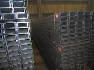
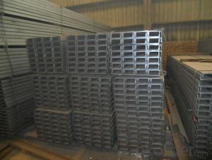
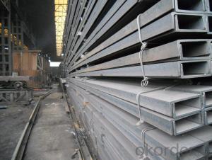
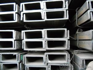
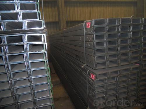
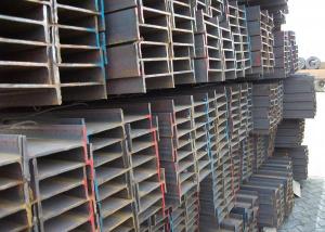
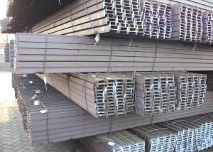
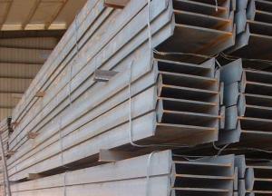
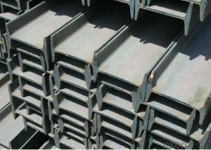
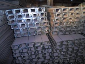
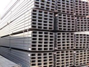
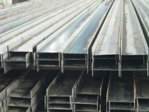
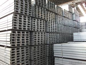
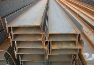
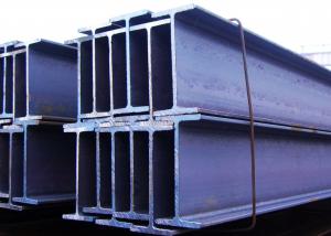
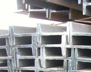
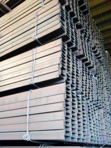
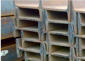
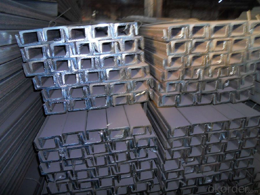
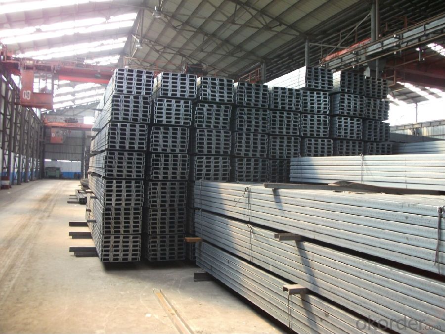
Hot Rolled Carbon Steel U-Channel with Many Standard
- Loading Port:
- Tianjin
- Payment Terms:
- TT or LC
- Min Order Qty:
- 20 m.t.
- Supply Capability:
- 1000 m.t./month
OKorder Service Pledge
OKorder Financial Service
You Might Also Like
Product Description:
OKorder is offering Hot Rolled Steel U-Channel at great prices with worldwide shipping. Our supplier is a world-class manufacturer of steel, with our products utilized the world over. OKorder annually supplies products to European, North American and Asian markets. We provide quotations within 24 hours of receiving an inquiry and guarantee competitive prices.
Product Applications:
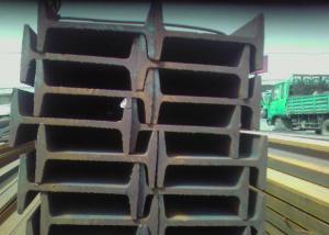
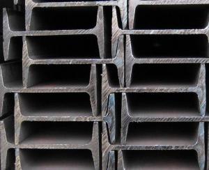
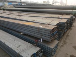
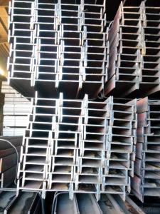
Hot Rolled Steel U-Channel can be applied to construction of warehouses, workshops, sport stadiums and car parks etc.The hot rolled channel steel belongs to carbon structural steel which is applied to in the field of construction and machinery.In details, the hot rolled channel steel is usually used for arch-itechtural structure, and they could be welded in order to support or hang a vari-ety of facilities. They are also usually used in combination with I beam. Generally,the hot rolled channel steel we supply must possess perfect welding property, riveting property and mechanical property and so on.
Product Advantages:
OKorder's Hot Rolled Steel U-Channel are durable, strong, and resist corrosion.
Main Product Features:
· Premium quality
· Prompt delivery & seaworthy packing (30 days after receiving deposit)
· Corrosion resistance
· Can be recycled and reused
· Mill test certification
· Professional Service
· Competitive pricing
Product Specifications:
We supply high quality MS Channel at reasonable price, including Chinese standard, Japanese standard and so on.
Standard | GB/JIS |
Material Grade | Q235,SS400 |
Technique: | Hot Rolled |
Sizes as per chinese standard: | 50*37*4.5mm - 300*89*11.5mm |
Sizes as per japanese standard: | 50*25*3mm – 200*80*7.5mm |
Length: | 6meter, 9meter, 12meter |
The chemical composition of HR Channel Steel according to Q235B
Alloy No | Grade | Element(%) | ||||
C | Mn | S | P | Si | ||
Q235 | B | 0.12-0.20 | 0.3-0.7 | ≦0.045 | ≦0.045 | ≦0.3 |
FAQ:
Q1: Why buy Materials & Equipment from OKorder.com?
A1: All products offered byOKorder.com are carefully selected from China's most reliable manufacturing enterprises. Through its ISO certifications, OKorder.com adheres to the highest standards and a commitment to supply chain safety and customer satisfaction.
Q2: How do we guarantee the quality of our products?
A2: We have established an advanced quality management system which conducts strict quality tests at every step, from raw materials to the final product. At the same time, we provide extensive follow-up service assurances as required.
Q3: How soon can we receive the product after purchase?
A3: Within three days of placing an order, we will begin production. The specific shipping date is dependent upon international and government factors, but is typically 7 to 10 workdays.
- Q: Channel and I-beam are commonly used in construction sites. It is better to have on-site construction drawings, thank you
- Channel and I-beam are usually used to build floors.
- Q: How do steel I-beams contribute to energy efficiency in buildings?
- Steel I-beams contribute to energy efficiency in buildings in several ways. Firstly, steel is a highly durable material that can withstand heavy loads, allowing for the construction of larger and taller buildings. This enables the use of efficient building designs, such as open floor plans and large windows, which maximize natural light and ventilation, reducing the need for artificial lighting and HVAC systems. Additionally, steel I-beams have a high strength-to-weight ratio, meaning they can support heavier loads with less material compared to other building materials. This allows for the construction of lighter and more efficient structures, reducing the overall energy consumption during construction and minimizing the environmental impact. Moreover, steel I-beams can be fabricated off-site with precision, reducing construction time and minimizing waste. This streamlined construction process further contributes to energy efficiency by reducing the energy required for on-site activities and minimizing construction-related carbon emissions. Lastly, steel is a recyclable material, and steel I-beams can be easily salvaged and reused in other construction projects. This promotes sustainability by reducing the demand for new steel production, which is an energy-intensive process. Overall, the use of steel I-beams in building construction enhances energy efficiency through their durability, lightweight nature, efficient fabrication process, and recyclability.
- Q: How do you calculate the deflection of a steel I-beam?
- By utilizing the principles of structural engineering and mechanics, one can determine the deflection of a steel I-beam. Deflection refers to the extent of bending or flexing that occurs when a load is applied to the beam. It is a crucial aspect to consider in the design of structures to guarantee their stability and safety. To calculate the deflection of a steel I-beam, the following steps can be undertaken: 1. Identifying the load: Initially, one must identify the type and magnitude of the load acting upon the beam. This could be a concentrated load, uniformly distributed load, or a combination of both. 2. Determining the reaction forces: The reaction forces at the supports of the beam must be determined. This can be done by considering the equilibrium of forces and moments acting on the beam. 3. Calculating the bending moment: The bending moment at any point along the length of the beam can be calculated using the principles of statics. This involves considering the distribution of the applied load and the geometry of the beam. 4. Finding the moment of inertia: The moment of inertia is a characteristic of the beam that describes its resistance to bending. It relies on the shape and dimensions of the cross-section of the beam. The moment of inertia can be determined using standard engineering reference tables or specific formulas for the I-beam shape. 5. Applying the beam deflection formula: The beam deflection formula varies depending on the type of load and the support conditions of the beam. For a simply supported beam under a concentrated load at the center, the deflection formula (δ) is given as δ = (5FL^4) / (384EI), where F represents the applied load, L is the length of the beam, E is the modulus of elasticity of the steel, and I is the moment of inertia. 6. Calculating the deflection: By utilizing the values derived from the previous steps, one can calculate the deflection of the steel I-beam. This will provide an indication of the extent to which the beam will bend or flex under the applied load. It is essential to note that this explanation offers a simplified overview of the calculation process. Additional factors such as beam supports, structural connections, and other loads acting on the beam may need to be taken into account. It is recommended to consult with a structural engineer or refer to relevant design codes and standards to ensure accurate and safe calculations.
- Q: What are the common welding techniques used for steel I-beams?
- Steel I-beams can be welded using a variety of techniques, including shielded metal arc welding (SMAW), gas metal arc welding (GMAW), and flux-cored arc welding (FCAW). SMAW, also known as stick welding, involves manually welding with a consumable electrode coated in flux. The flux creates a protective shield that prevents contamination. It is a versatile technique that can be used in different positions and is commonly used for welding structural steel, including I-beams. GMAW, or MIG welding, is a semi-automatic process that uses a continuous solid wire electrode and a shielding gas. It offers fast welding speeds and precise control over the weld pool. GMAW is often preferred for welding steel I-beams due to its efficiency and ability to produce high-quality welds. FCAW is similar to GMAW, but it uses a hollow tubular electrode filled with flux. This eliminates the need for an external shielding gas, making it a cost-effective option. FCAW is commonly used for thicker steel I-beams or in outdoor environments where wind may affect the shielding gas. In some cases, specialized techniques like submerged arc welding (SAW) or laser beam welding (LBW) may be used for specific applications or in larger industrial settings. These techniques offer unique advantages such as higher deposition rates or precise control, but they are less commonly used in standard steel I-beam welding. Ultimately, the choice of welding technique depends on factors such as the thickness of the I-beam, desired weld quality, efficiency, and environmental conditions. Skilled welders and engineers can determine the most suitable technique based on these considerations to ensure strong and durable welds on steel I-beams.
- Q: What are the common design codes and standards applied to steel I-beams?
- The common design codes and standards applied to steel I-beams include the American Institute of Steel Construction (AISC) Manual of Steel Construction, which provides guidelines for design, fabrication, and erection of steel structures. Additionally, the International Building Code (IBC) and American Society of Civil Engineers (ASCE) 7 Standard for Minimum Design Loads for Buildings and Other Structures outline the minimum requirements for structural design and load calculations. These codes and standards ensure the safety and reliability of steel I-beam structures.
- Q: How do steel I-beams contribute to the overall safety of a structure?
- A structure's overall safety is enhanced in numerous ways by the presence of steel I-beams. To begin with, their design and construction make them exceptionally strong and capable of withstanding bending or twisting forces. Consequently, they are able to bear heavy loads and distribute weight evenly across the structure. By providing a robust and stable framework, steel I-beams decrease the likelihood of structural collapse, guaranteeing the safety of the occupants. In addition, steel I-beams possess a significant level of fire resistance. Since steel has a high melting point, it can endure elevated temperatures for longer periods compared to materials like wood or concrete. This fire resistance diminishes the risk of structural failure during a fire, allowing occupants more time to safely evacuate the building. Furthermore, steel I-beams are exceptionally durable and long-lasting, displaying a high resistance to corrosion and degradation. This ensures that the structure remains intact and stable over time, reducing the chance of sudden failures or collapses. The strength and durability of steel I-beams also make them less susceptible to natural disasters such as earthquakes or strong winds, further bolstering the safety of the structure. In conclusion, steel I-beams contribute to the overall safety of a structure through their provision of a strong and stable framework, high fire resistance, and durability. Their ability to withstand heavy loads, distribute weight evenly, and resist bending or twisting forces guarantees the structural integrity of the building, minimizing the risk of collapse. When combined with their fire resistance and durability, steel I-beams offer a reliable and secure foundation for a safe structure.
- Q: What is the weight range of steel I-beams?
- The weight range of steel I-beams can vary depending on the specific dimensions and length of the beam. However, as a general guideline, the weight range typically falls between 6 pounds per foot (8.9 kilograms per meter) for smaller beams and can go up to 260 pounds per foot (386 kilograms per meter) for larger and heavier beams. It's important to note that these weight ranges are approximate and can vary based on the specific grade and type of steel used in the construction of the I-beam. Additionally, the weight range can also be influenced by any additional modifications or features that may be present, such as holes or cut-outs, which can reduce the weight of the beam.
- Q: What are the advantages of using steel I-beams?
- There are several advantages of using steel I-beams in construction projects. Firstly, steel I-beams are known for their exceptional strength and durability. They have a high load-carrying capacity, allowing them to support heavy loads and withstand extreme weather conditions. This makes them suitable for a wide range of applications, including bridges, buildings, and industrial structures. Secondly, steel I-beams offer design flexibility. They come in various sizes and shapes, allowing engineers and architects to customize them according to the specific requirements of the project. This versatility makes it easier to create complex structures and optimize the use of space. Additionally, steel I-beams are fire-resistant. Due to their high melting point, they can withstand high temperatures better than other materials such as wood or concrete. This can be a crucial advantage in terms of safety, as it provides additional time for evacuation and containment in case of a fire. Furthermore, steel I-beams require minimal maintenance. Unlike wood, which can rot or be susceptible to pests, steel is not prone to such issues. This translates into cost savings over the long term, as there is no need for regular repairs or replacements. Another advantage of steel I-beams is their eco-friendliness. Steel is a highly recyclable material, and the use of recycled steel in construction projects helps to reduce the demand for new raw materials and lowers carbon emissions. Additionally, steel I-beams can be easily dismantled and reused in other projects, further contributing to sustainability efforts. Lastly, steel I-beams provide excellent structural integrity. They have consistent dimensions and properties, ensuring uniformity and reliability in the construction process. This makes them a preferred choice for engineers and builders who prioritize safety and stability. In conclusion, the advantages of using steel I-beams in construction include their strength, design flexibility, fire resistance, low maintenance requirements, eco-friendliness, and structural integrity. These factors make steel I-beams a reliable and efficient choice for a wide range of construction projects.
- Q: Can steel I-beams be used for manufacturing plants?
- Yes, steel I-beams can be used for manufacturing plants. They are commonly used in the construction of industrial buildings due to their high structural strength and load-bearing capabilities. Steel I-beams provide the necessary support and stability required for the heavy machinery and equipment found in manufacturing plants.
- Q: Are steel I-beams prone to rust or corrosion?
- Yes, steel I-beams are prone to rust and corrosion. Steel is primarily made from iron, which is highly susceptible to rusting when exposed to moisture and oxygen. Over time, if not properly protected, the steel I-beams can develop rust and corrosion, which weakens their structural integrity. To prevent this, various protective coatings and treatments such as galvanization or painting are applied to the steel beams. These coatings act as a barrier, preventing moisture and oxygen from reaching the underlying steel and reducing the risk of rust and corrosion. Regular maintenance and inspection are also essential to identify and address any signs of rust or corrosion early on to ensure the continued strength and stability of the I-beams.
Send your message to us
Hot Rolled Carbon Steel U-Channel with Many Standard
- Loading Port:
- Tianjin
- Payment Terms:
- TT or LC
- Min Order Qty:
- 20 m.t.
- Supply Capability:
- 1000 m.t./month
OKorder Service Pledge
OKorder Financial Service
Similar products
Hot products
Hot Searches
Related keywords
