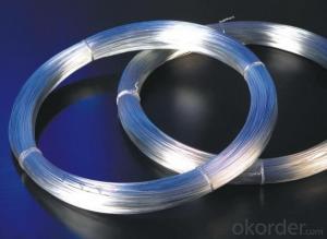
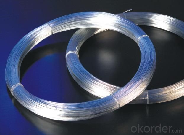
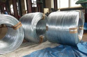
High Quality Electro Galvanized Iron Wire With High Quality
- Ref Price:
-

- Loading Port:
- Tianjin
- Payment Terms:
- TT OR LC
- Min Order Qty:
- 5 m.t.
- Supply Capability:
- 100 m.t./month
OKorder Service Pledge
Quality Product, Order Online Tracking, Timely Delivery
OKorder Financial Service
Credit Rating, Credit Services, Credit Purchasing
You Might Also Like


Specifications
1.The lowest price
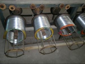
2.Have machine to produce
3.Materials test report
4.As customer's require
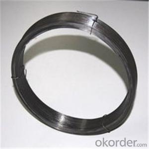
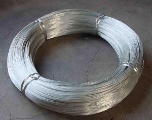
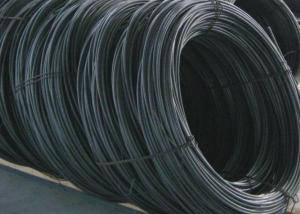
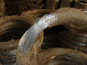
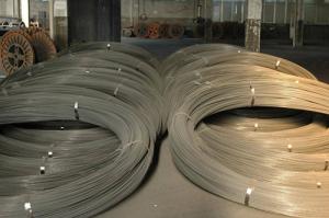
Silvery and soft binding wire
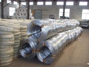
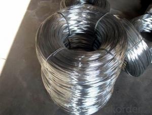
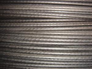
Galvanized metal wire
Material: low carbon steel
Surface treatment: galvanized
Gauge | SWG | BWG | Metric systems |
8# | 4.06 | 4.19 | 4.0 |
9# | 3.66 | 3.76 | |
10# | 3.25 | 3.40 | 3.50 |
11# | 2.95 | 3.05 | 3.00 |
12# | 2.64 | 2.77 | 2.80 |
13# | 2.34 | 2.41 | 2.50 |
14# | 2.03 | 2.11 | |
15# | 1.83 | 1.83 | 1.80 |
16# | 1.63 | 1.65 | 1.65 |
17# | 1.42 | 1.47 | 1.40 |
18# | 1.22 | 1.25 | 1.20 |
19# | 1.02 | 1.07 | 1.00 |
20# | 0.91 | 0.89 | 0.90 |
21# | 0.81 | 0.813 | 0.80 |
22# | 0.71 | 0.711 | 0.70 |
- Q: So I customized my guitar, and now I need to wire it. i have a pre-wired pickguard but I don't know how to actually hook it up. There's 3 wires. I have 2 humbuckers, 1 singlecoil, 1 tone, and 1 volume. All I know is that one wire gets soldered to the back where the springs are and another wire goes to the input jack. But there's a 3rd wire and I don't know where it goes. I don't even know which wire goes to what. Please don't post a diagram because it doesn't help. I think the wire colors are white, blue, and yellow. Please help!
- OK...I okorder /... That should hook you up.
- Q: Im replacing the factory rear speakers in my car but cant figure on which wires are positive and which are negative. I went on a site for impalas but the color wires they have listed are not the same color wires in my car your help will be appreciated.
- Left Rear Speaker Positive Wire (+): Brown Left Rear Speaker Negative Wire (-): Yellow Right Rear Speaker Positive Wire (+): Dark Blue Right Rear Speaker Negative Wire (-): Light Blue
- Q: Both wires are green but unsure if it is the top or bottom wire.
- go to autozone and get a test light (looks like a screwdriver with a light in the handle and a ground) ground it and poke it on each wire, light lights up you got the hot one.
- Q: who knows the use of wire mesh? Actually where does the wire mesh be used?
- wire okorder
- Q: Is there really a difference between audio wire and regular house wire? If you say yes then please explain, in understandable scientific terms why, or point me to a site that can.
- yes. even bigger difference when you used it to wire the battry to the amp. The solid-copper house wire are design for high voltage and lov current. But, your car voltage is low, only 12 volts. Now see if you have a big amp and use 1000 watts. and calculate with the Power formula : P = V x I P stands for Power, V stands for Voltage, and I stands for Current. The currents you use in 12 volts equals 83.333 ampere. its a big current. now if you use the home voltage(220 volts) the currents equal 4.545 ampere. See the different? 83 ampere and 4 ampere. that is why the wire for car amp/subwoofer usually not use solid copper, but use hairsize copper. Of course not a single hairsize copper, but alot of it. I have a car with audio system. I use 1 swiss audio power amp 2000 watts and 2 poweramper 1500 rms Sub. and to wire the battery and the amp, I used a thumb size cable - hairsize copper.
- Q: The wire from the pinball machine only has two wires. How do I rewire the machine with a grounded wire and plug?
- Used to love to play pinball in this one bar that would give you a beer if you got so many points. I got good at pinball. (That was back in my drinky too much days.) Funny thing is, I can't play worth a damn now that I'm sober. I went to this great arcade with my nephews a year and a half ago - big ol' thing on the Oregon coast - and am looking forward to doing it again this summer. I love arcades, but we don't have one where I live now.
- Q: Hello,I got a ventilation fan for the bathroom. The fan has 2 wires and there are 2 wires sticking out of the wall.How do I know which wire connects to which wire?What would happen if I connect the wrong wires?
- Check the voltage with a meter. If correct just wire it. At one time in the US the wiring wasn't color coded. Not the safest but it worked!
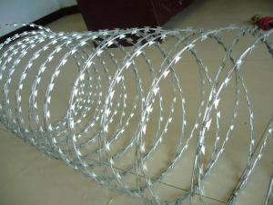
- Q: What are the types of Barbed wires?
- Barbed wire is a sharp, twisted form of wire which is used mainly for protection and containment. Barbed wire is twisted at various stages to create sharp points which can create an instant injury if scaled. There are several different types of barbed wire. Classic Classic barbed wire is also the cheapest available. It is made of either steel or aluminum. The wire is twisted at sequential stages to create sharp points. Classic barbed wire will be used to keep animals in a specific area or to keep people away from a protected area. Razor Wire Razor barbed wire is used to line the walls of prisons and containment facilities. This wire is made by cutting large strips of aluminum with a sharp triangular blade on each side of the wire strip. These blades are extremely sharp. They are intended to cause much greater injury than a piece of classic barbed wire. Razor wire is often used to protect business premises from intruders. Spiral Spiral barbed wire is formed with a sharp blade running parallel to a piece of normal steel. This is then twisted into a spiral shape to create a long and continuous sharp edge to the wire. Spiral wire is often used for army exercises and for other containment or protection purposes. I hope this quite help u... thank u. :-)
- Q: I am buying my sister Interior Underdash lights for her car, but it says it requires a quot;hard wire installationbecause it does not come with an on and off switch. What exactly does that mean? Will the lights turn on and off according to whether the car is on or off? Also, what is a hard wire installation?
- Hard wire means it's not just plugged in. eg. using the cigarette lighter but instead is permanently wired in. All you need to do is wire the lights ground wire to any ground wire under the dash eg. ignition ground or radio ground ( wire will be black ) or directly to a screw that goes into any metal part of the chassis and wire the lights positive wire to either the accessory wire from your ignition (lights come on when car is on) or a constant power wire eg. radio power wire and wire in a toggle switch so you can turn the lights on or off at will.
- Q: want to get ready to solderis the fuzzy stuff the wire? or the shiny (positive green and negative red color) the wire? sorry i know its a noob questionlet me knowthanks
- wire is metal and metal is orange or silver . The fussy stuff is string
Send your message to us
High Quality Electro Galvanized Iron Wire With High Quality
- Ref Price:
-
- Loading Port:
- Tianjin
- Payment Terms:
- TT OR LC
- Min Order Qty:
- 5 m.t.
- Supply Capability:
- 100 m.t./month
OKorder Service Pledge
Quality Product, Order Online Tracking, Timely Delivery
OKorder Financial Service
Credit Rating, Credit Services, Credit Purchasing
Similar products

Hot products
Hot Searches

