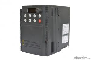
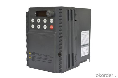
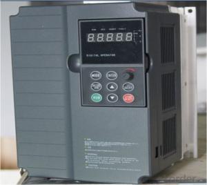
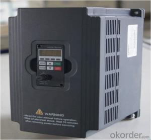
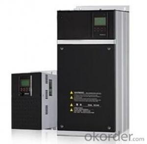
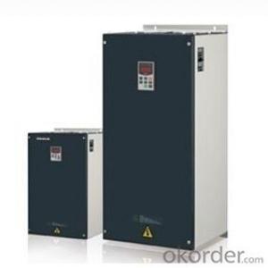
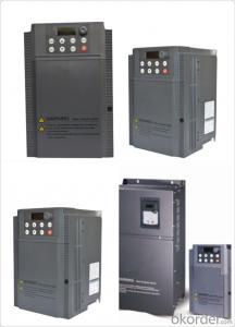
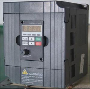
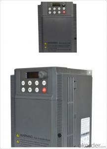
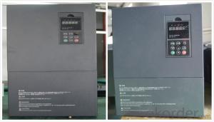
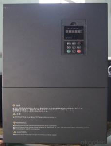
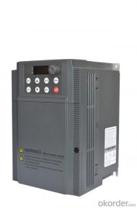
Frequency Inverter Single-phase 380V class 55KW
- Ref Price:
-

- Loading Port:
- Tianjin
- Payment Terms:
- TT OR LC
- Min Order Qty:
- 1 pc
- Supply Capability:
- 100000 pc/month
OKorder Service Pledge
OKorder Financial Service
You Might Also Like


Specifications
1.220V Single Phase Variable Frequency Drive 2.2KW
2.Advanced control technology
3.Easy to operate
General
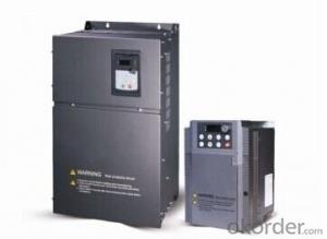
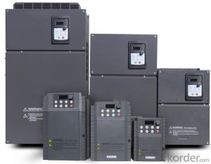
CNBM frequency inverter is a high-quality, multi-function,
low-noise variable frequency drive which is designed, developed and manufactured according to international standards.
It can meet different needs of industrial conditions.
The inverter applies advanced control technology of space voltage vector PWM, with functions of constant voltage control, power-off restart, dead zone compensation, automatic torque compensation, online modification parameter, high-speed impulse input, simple PLC and traverse.

Product Name:CMAX-VCG15/P18.5T3 ~ CMAX-VCG18.5/P22T3
Application
Textile: coarse spinner, spinning frame, wrap-knitting machine, loom, knitting machine, silk-spinning machine, etc.
Plastic: extruder, hauling machine, decorating machine, etc.
Pharmacy: mixer, roaster, etc.
Woodworking: engraving machine, sander, veneer peeling lathe, etc.
Papermaking: single type papermaking machine, etc.
Machine tool: non-core grinding machine, optical lens grinding machine, cutting mill, etc.
Printing: cloth-washing machine, dye vat, etc.
Cement: feeder, air blower, rotary furnace, mixer, crusher, etc
Fan and pump: kinds of fans, blowers and pumps
Specification
Item | Specification | |
Input | Input voltage | 220/380V±15% |
Input frequency | 47~63Hz | |
Output | Output voltage | 0~input voltage |
Output frequency | 0~600Hz | |
Peripheral interface characteristics | Programmable digital input | 4 switch input, 1 high-speed impulse input |
Programmable analog input | AI1: 0~10V input AI2: 0~10V input or 0~20mA input, | |
Programmable open collector output | 2 Output (3.7kW and above: 1 Open collector output) | |
Relay Output | 1 Output (3.7kW and above: 2 Relay output) | |
Analog output | 2 Output, one is 0~10V, another is 0~20mA or 0~10V | |
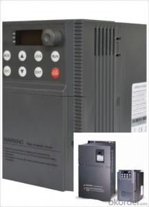
Keypad | Display:5-digit 8-section LED (Red), 2 indicators; parameter setting: 8 keys (including multi-function hot key ), 1 potentiometer | |
Technical performance characteristics | Control mode | All digital space voltage vector SVPWM algorism |
Overload capacity | G purpose: 150% rated current 60s P purpose: 120% rated current 60s | |
Speed ratio | 1: 100 | |
Carrier frequency | 1.0~10.0kHz | |
Torque compensation | Linear, multi-point, 1.3th power, 1.7th power, 2.0th power reduced torque; Compensation voltage range: automatic compensation and manual compensation 0.1~10% | |
Automatic voltage adjustment | It can automatically maintain output voltage constant when grid voltage fluctuates. | |
Automatic current adjustment | When the current is over current limit, under clocking automatically limits output current. | |
Function characteristics | Frequency setting mode | Keypad digital analog input, keypad potentiometer, impulse frequency, communication, multi-step speed and simple PLC, PID setting and so on, switch-over of setting modes. |
Simple PLC, multi-step speed control | 16-step speed control | |
Special function | Traverse control, length control, time control | |
QUICK/JOG key | User-defined multi-function hot key | |
Protection function | Over-current, Over voltage, under-voltage, over-heat, phase failure, over-load and motor over-load | |
Working condition | Installation site | Indoor, altitude of less than 1km, dust free, non-corrosive gases, no direct sunlight |
Application environment | -10°C~+40°C, 20~90%RH (no dew) | |
Vibration | Less than 0.5g | |
Storage temperature | -25°C~+65°C | |
Installation type | Wall-mounted type, floor cabinet type | |
Cooling mode | Air-forced cooling | |
- Q: Why does the frequency converter cause interference?
- (a) PE converter main circuit terminals (E, G) must be grounded, the motor can be grounded and the inverter with the common ground, but not with other equipment, must play ground pile, and the ground should take place far away from electrical equipment. At the same time, the cross-sectional area of the grounding wire of the converter shall be no less than 4mm2, and the length shall be within 20m.(b) in the ground wire of other electromechanical equipment, the protective earthing and the work earthing shall be separately provided with grounding electrodes, and finally shall be imported to the electrical position of the distribution cabinet. The shield of the control signal and the shielding of the main circuit wire shall also be separately provided with earth electrodes, and finally shall be incorporated into the electrical junction of the distribution cabinet.
- Q: First of all, I would like to achieve the frequency converter with motor static linear acceleration, high-speed linear deceleration stop processFirst question: I say kind of situation, three paragraph speed start, 0.1hz---> high 30hz-->0.1hzSecond problem: manual speed instruction 1, speed 2, speed 3 instruction instruction I want to use PLC to control three speed motor with three reverse contact dry. I understand speed instruction 1 is switched on (2, 3 connected) transmission section set the frequency with the frequency segment set 0HZ123 AssociationThird questions: manual section, speed command, main frequency and STEP1-STEP7 stage setting frequency, I use PLC analog to the frequency main frequency setting, plus and deceleration, STEP1-7 are set 0, can achieve what I wantInitial contact frequency converter, home pointing
- Three speed motor static acceleration setting speed, then slow down to stop, in fact, frequency case should be motor frequency 30Hz set frequency converter 30Hz, and then to start and stop signal requirements (plus or minus speed, according to the scene set P-10 P-11)
- Q: What is the main function of the frequency converter on the machine tools?
- The following example to three inverter in the application of the note for example!CNC machine tool is a kind of flexible and efficient automatic machine tool. It can solve the complicated, precise and small batch processing problem. It is very important to improve the machining accuracy and efficiency of CNC machine tools by rationally controlling the spindle of NC machine tools.
- Q: What is the upper and lower limit of the environmental temperature to ensure the normal operation of the inverter?
- Inverter environment temperature(1) working temperature. The use of frequency converter should pay attention to the environmental matters, the internal is high-power electronic components, is easily affected by the operating temperature, the product is generally required to be 0~55 degrees, but in order to ensure safe and reliable work, when usedShould be considered under the best control in 40 DEG C. In the control box, the inverter shall be installed on the upper part of the box, and strictly comply with the installation requirements of the product manual, absolutely not allowed to sendA heat element or a heat generating element is mounted close to the bottom of the inverter.
- Q: 5.5KW frequency converter with 4.5KW deep water pump, pressure regulator by conveying signal to frequency converter start normal, the pressure to reduce the frequency converter after the start, to about 30Hz in order to maintain the pressure about shocks, 30 seconds inverter over-current alarm. Can it be the fault of the frequency converter? How should I check it?
- overloadOverload faults include frequency overload and motor overload. It may be caused by the acceleration time is too short, the network voltage is too low and the load is too heavy. Generally by extending the acceleration time, extending the braking time, check the power grid voltage. Overload, the selected motor and inverter can not drag the load, or it may be caused by poor mechanical lubrication. Such as the former, you must replace the high-power motor and inverter; if the latter is to overhaul the production machinery.
- Q: What is the frequency converter AVR?
- Automatic adjustment function: AVR voltage inverter based on voltage feedback, automatically adjust the output voltage, which is not affected by the grid voltage and load change, to protect the motor from excessive voltage caused by long-term insulation damage or high magnetic density caused by excessive heating core.
- Q: Can a power converter be used in a motor with small power? Will it burn the motor?
- Yes, but you have to set some parameters that correspond to changes in the motor to play a protective role
- Q: Frequency converter OC alarm, what's the matter?
- And some did not inform you of the inverter fault category, when the OC boot failure, will cause greater danger, then simply caused by surface phenomenon similar to program crashes, such as the P9/G9 series machine when the machine detects INVT, module failure, operationThe H00 character appears on the panel, and all key actions are rejected. Unknown insider will think: program crash, CPU motherboard is a problem.
- Q: What are the contents of frequency converter maintenance?
- Replacement of spare partsThe inverter consists of various components, some parts of the work for a long time after its performance will gradually decrease, aging, which is the main reason of inverter fault, in order to ensure the normal operation of equipment for a long time, the device should be replaced regularly:
- Q: How to choose frequency converter?
- Inverter by internal IGBT drive voltage and frequency off to adjust the output power, the power supply voltage required to provide according to the actual needs of the motor, so as to achieve the purpose of speed, energy saving, in addition, there are a lot of protection drive, such as over-current, over-voltage, overload protection and so on. With the continuous improvement of the degree of industrial automation, inverter has also been widely used.
Send your message to us
Frequency Inverter Single-phase 380V class 55KW
- Ref Price:
-
- Loading Port:
- Tianjin
- Payment Terms:
- TT OR LC
- Min Order Qty:
- 1 pc
- Supply Capability:
- 100000 pc/month
OKorder Service Pledge
OKorder Financial Service
Similar products

Hot products

Hot Searches
Related keywords

