
AC Driver China Best Selling VFD Variable Frequency Drive 3 phase 380V
- Ref Price:
-

- Loading Port:
- Tianjin
- Payment Terms:
- TT OR LC
- Min Order Qty:
- 1 pc
- Supply Capability:
- 100000 pc/month
OKorder Service Pledge
OKorder Financial Service
You Might Also Like


Specifications
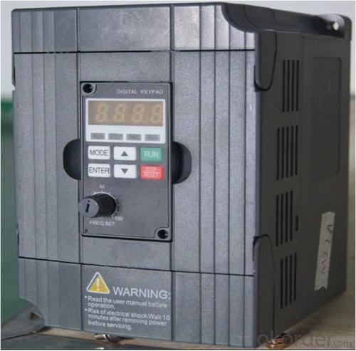
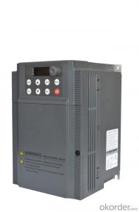
1.220V Single Phase Variable Frequency Drive 2.2KW
2.Advanced control technology
3.Easy to operate
220V Single Phase Variable Frequency Drive 2.2KW
General
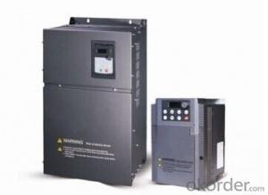
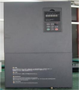
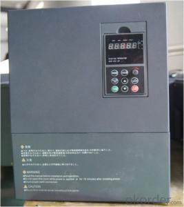
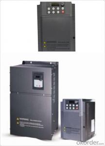
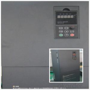
CNBM frequency inverter is a high-quality, multi-function,
low-noise variable frequency drive which is designed, developed and manufactured according to international standards.
It can meet different needs of industrial conditions.
The inverter applies advanced control technology of space voltage vector PWM, with functions of constant voltage control, power-off restart, dead zone compensation, automatic torque compensation, online modification parameter, high-speed impulse input, simple PLC and traverse.
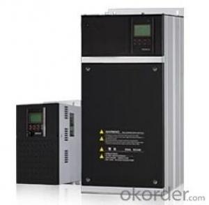
Product Name:CMAX-VCG15/P18.5T3 ~ CMAX-VCG18.5/P22T3
Application
Textile: coarse spinner, spinning frame, wrap-knitting machine, loom, knitting machine, silk-spinning machine, etc.
Plastic: extruder, hauling machine, decorating machine, etc.
Pharmacy: mixer, roaster, etc.
Woodworking: engraving machine, sander, veneer peeling lathe, etc.
Papermaking: single type papermaking machine, etc.
Machine tool: non-core grinding machine, optical lens grinding machine, cutting mill, etc.
Printing: cloth-washing machine, dye vat, etc.
Cement: feeder, air blower, rotary furnace, mixer, crusher, etc
Fan and pump: kinds of fans, blowers and pumps
Specification
Item | Specification | |
Input | Input voltage | 220/380V±15% |
Input frequency | 47~63Hz | |
Output | Output voltage | 0~input voltage |
Output frequency | 0~600Hz | |
Peripheral interface characteristics | Programmable digital input | 4 switch input, 1 high-speed impulse input |
Programmable analog input | AI1: 0~10V input AI2: 0~10V input or 0~20mA input, | |
Programmable open collector output | 2 Output (3.7kW and above: 1 Open collector output) | |
Relay Output | 1 Output (3.7kW and above: 2 Relay output) | |
Analog output | 2 Output, one is 0~10V, another is 0~20mA or 0~10V | |
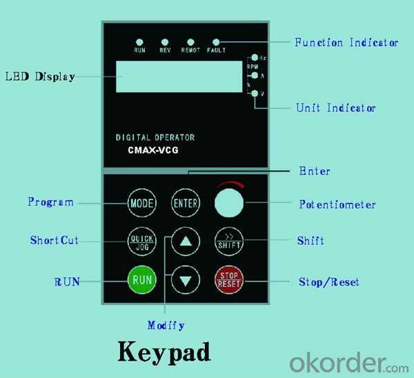
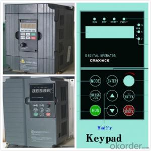
Keypad | Display:5-digit 8-section LED (Red), 2 indicators; parameter setting: 8 keys (including multi-function hot key ), 1 potentiometer | |
Technical performance characteristics | Control mode | All digital space voltage vector SVPWM algorism |
Overload capacity | G purpose: 150% rated current 60s P purpose: 120% rated current 60s | |
Speed ratio | 1: 100 | |
Carrier frequency | 1.0~10.0kHz | |
Torque compensation | Linear, multi-point, 1.3th power, 1.7th power, 2.0th power reduced torque; Compensation voltage range: automatic compensation and manual compensation 0.1~10% | |
Automatic voltage adjustment | It can automatically maintain output voltage constant when grid voltage fluctuates. | |
Automatic current adjustment | When the current is over current limit, under clocking automatically limits output current. | |
Function characteristics | Frequency setting mode | Keypad digital analog input, keypad potentiometer, impulse frequency, communication, multi-step speed and simple PLC, PID setting and so on, switch-over of setting modes. |
Simple PLC, multi-step speed control | 16-step speed control | |
Special function | Traverse control, length control, time control | |
QUICK/JOG key | User-defined multi-function hot key | |
Protection function | Over-current, Over voltage, under-voltage, over-heat, phase failure, over-load and motor over-load | |
Working condition | Installation site | Indoor, altitude of less than 1km, dust free, non-corrosive gases, no direct sunlight |
Application environment | -10°C~+40°C, 20~90%RH (no dew) | |
Vibration | Less than 0.5g | |
Storage temperature | -25°C~+65°C | |
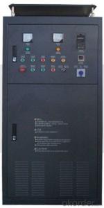
Installation type | Wall-mounted type, floor cabinet type | |
Cooling mode | Air-forced cooling | |
- Q: That is, some parameters of the inverter, such as torque, current, frequency, etc., are displayed on the Kingview software interface, but not through the PLC. The idea that the MODBUS protocol between SIEMENS and 200PLC has never been successful before, so that's the idea of the ABB. If it can be achieved,Is it necessary to write the script program on the Kingview, and what problems should I pay attention to when using the MODBUS protocol in Kingview software?The problem is a little bit more, I hope the experts teach me this rookie! Thank you
- As long as there are 485 communications can be, the frequency converter manual on the MODBUS protocol, the address of each parameter, in the king view on the link can do, and I hope to adopt.
- Q: First of all, I would like to achieve the frequency converter with motor static linear acceleration, high-speed linear deceleration stop processFirst question: I say kind of situation, three paragraph speed start, 0.1hz---> high 30hz-->0.1hzSecond problem: manual speed instruction 1, speed 2, speed 3 instruction instruction I want to use PLC to control three speed motor with three reverse contact dry. I understand speed instruction 1 is switched on (2, 3 connected) transmission section set the frequency with the frequency segment set 0HZ123 AssociationThird questions: manual section, speed command, main frequency and STEP1-STEP7 stage setting frequency, I use PLC analog to the frequency main frequency setting, plus and deceleration, STEP1-7 are set 0, can achieve what I wantInitial contact frequency converter, home pointing
- Using PLC to analog converter control input frequency up to speed off from the requirements of the inverter frequency source set P-00 speed by 00 digital operation panel to analog frequency PLC given 0102 given frequency parameters can choose the set of 01 or 02 and the period of quick closing even P-17P-19 parameters affect analog control
- Q: The frequency converter is in use suddenly the speed reduces, then the debugging is out of control, how to do?
- Excessive voltage generation and regenerative braking, the so-called inverter over-voltage, refers to a variety of reasons caused by inverter voltage exceeds the rated voltage, concentrated in the DC bus frequency converter DC voltage. In normal operation, the DC part voltage of converter is the average value after three-phase full wave rectification.
- Q: Today, I was asked the question, and I also brought it to you to share the following Oh!
- The frequency of the electricity we use everyday is 50Hz. If we want to change the frequency, we have to change it through the frequency converter.The working principle of frequency converter is to change the frequency alternating current into no frequency direct current, and then control it by electronic circuit so that it can adjust its frequency alternating current at any time.The inverter is similar to the back half of the inverter, which converts the direct current into alternating current.
- Q: Ask, what is the ratio of frequency converter?
- Rotating main potentiometer, respectively, to see the three frequency converter F1.00 parameters, keyboard digital display reference input, follow potentiometer changes, and the proportion of 1:1.5:2. Rotate three trimmer potentiometers respectively, and the reference input of the corresponding converter has little change.
- Q: What is a frequency converter?
- There are many classifications of inverter, the main circuit according to the classification, can be divided into voltage type inverter and current source inverter; switching mode in accordance with the classification, can be divided into PAM control inverter, PWM control frequency and high frequency PWM inverter control; in accordance with the principle of classification, can be divided into V/f control inverter, slip frequency control inverter and vector control inverter; according to use classification, can be divided into general inverter, high performance inverter, high frequency inverter, single-phase inverter and three-phase inverter.
- Q: PT100 temperature patrol instrument, when the converter is not open, the measurement is normal. Once opened, it shows completely disorder, and sometimes there are puzzling characters. How can I solve this problem? Please enlighten master!
- To clear the train of thought, in order to achieve the normal work of the temperature detector, it is impractical to test the inverter. So what we can do, basically, is shielding, filtering, grounding, and the like.
- Q: What is the difference between inverter energy consumption braking and motor energy consumption braking?
- The reverse brake has one of the biggest disadvantages: when the motor speed is 0, if the power supply is not removed in time, the motor will reverse. There are two methods to solve this problem: 1, in the control loop of the motor power supply phase, adding a time relay, when the brake after a period of time, disconnect the power after inversion, so as to avoid motor reversal. But the braking time is difficult to estimate because of this method, so the braking effect is not accurate. 2. A speed relay is added to the control circuit of the motor's inverting power supply. When the sensor detects the speed of the motor is 0, the inverter power of the motor is cut off in time. Because of this method, the speed relay monitors the motor speed in real time, so the braking effect is much better than the last one. It is precisely because reverse braking has this characteristic, therefore, it is not allowed to reverse the machinery, such as some lathes, etc., the brake method can not use reverse braking, and can only use energy consumption braking or mechanical brake.
- Q: What is the TTK converter produced?
- TTK inverter is made in Zhejiang.TTK series general frequency converter is a high quality, multi-function and low-noise converter developed and produced independently by our own. Its rich functions fully meet the various needs;
- Q: Can a power converter be used in a motor with small power? Will it burn the motor?
- If it is overloaded with constant torque, the vector control or DTC, then not power motor inverter below 1/4, otherwise the inverter to motor "modeling" is not accurate, easy to control and protection of the disorder is not perfect.
Send your message to us
AC Driver China Best Selling VFD Variable Frequency Drive 3 phase 380V
- Ref Price:
-
- Loading Port:
- Tianjin
- Payment Terms:
- TT OR LC
- Min Order Qty:
- 1 pc
- Supply Capability:
- 100000 pc/month
OKorder Service Pledge
OKorder Financial Service
Similar products

Hot products
Hot Searches
Related keywords

