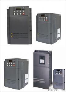
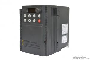
Variable Frequency Drive 3 phase 5.5kw 380V
- Ref Price:
-

- Loading Port:
- Tianjin
- Payment Terms:
- TT OR LC
- Min Order Qty:
- 1 pc
- Supply Capability:
- 100000 pc/month
OKorder Service Pledge
OKorder Financial Service
You Might Also Like


Specifications
1.220V Single Phase Variable Frequency Drive 2.2KW
2.Advanced control technology
3.Easy to operate
General
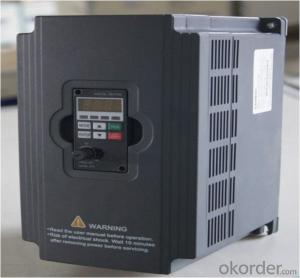
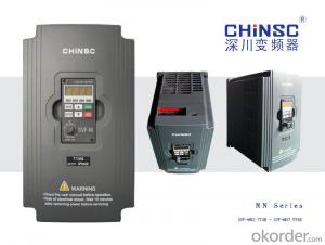
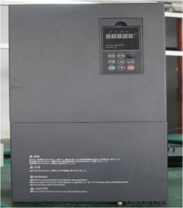
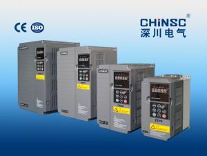
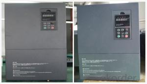
CNBM frequency inverter is a high-quality, multi-function,
low-noise variable frequency drive which is designed, developed and manufactured according to international standards.
It can meet different needs of industrial conditions.
The inverter applies advanced control technology of space voltage vector PWM, with functions of constant voltage control, power-off restart, dead zone compensation, automatic torque compensation, online modification parameter, high-speed impulse input, simple PLC and traverse.

Specification
Item | Specification | |
Input | Input voltage | 220/380V±15% |
Input frequency | 47~63Hz | |
Output | Output voltage | 0~input voltage |
Output frequency | 0~600Hz | |
Peripheral interface characteristics | Programmable digital input | 4 switch input, 1 high-speed impulse input |
Programmable analog input | AI1: 0~10V input AI2: 0~10V input or 0~20mA input, | |
Programmable open collector output | 2 Output (3.7kW and above: 1 Open collector output) | |
Relay Output | 1 Output (3.7kW and above: 2 Relay output) | |
Analog output | 2 Output, one is 0~10V, another is 0~20mA or 0~10V | |
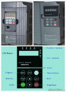
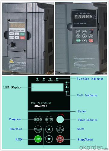
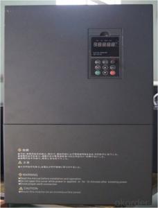
Keypad | Display:5-digit 8-section LED (Red), 2 indicators; parameter setting: 8 keys (including multi-function hot key ), 1 potentiometer | |
Technical performance characteristics | Control mode | All digital space voltage vector SVPWM algorism |
Overload capacity | G purpose: 150% rated current 60s P purpose: 120% rated current 60s | |
Speed ratio | 1: 100 | |
Carrier frequency | 1.0~10.0kHz | |
Torque compensation | Linear, multi-point, 1.3th power, 1.7th power, 2.0th power reduced torque; Compensation voltage range: automatic compensation and manual compensation 0.1~10% | |
Automatic voltage adjustment | It can automatically maintain output voltage constant when grid voltage fluctuates. | |
Automatic current adjustment | When the current is over current limit, under clocking automatically limits output current. | |
Function characteristics | Frequency setting mode | Keypad digital analog input, keypad potentiometer, impulse frequency, communication, multi-step speed and simple PLC, PID setting and so on, switch-over of setting modes. |
Simple PLC, multi-step speed control | 16-step speed control | |
Special function | Traverse control, length control, time control | |
QUICK/JOG key | User-defined multi-function hot key | |
Protection function | Over-current, Over voltage, under-voltage, over-heat, phase failure, over-load and motor over-load | |
Working condition | Installation site | Indoor, altitude of less than 1km, dust free, non-corrosive gases, no direct sunlight |
Application environment | -10°C~+40°C, 20~90%RH (no dew) | |
Vibration | Less than 0.5g | |
Storage temperature | -25°C~+65°C | |
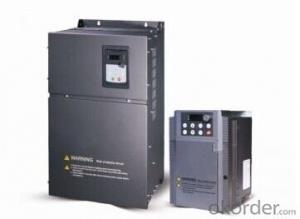
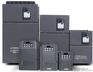
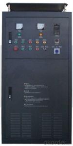
Installation type | Wall-mounted type, floor cabinet type | |
Cooling mode | Air-forced cooling | |
Application
Textile: coarse spinner, spinning frame, wrap-knitting machine, loom, knitting machine, silk-spinning machine, etc.
Plastic: extruder, hauling machine, decorating machine, etc.
Pharmacy: mixer, roaster, etc.
Woodworking: engraving machine, sander, veneer peeling lathe, etc.
Papermaking: single type papermaking machine, etc.
Machine tool: non-core grinding machine, optical lens grinding machine, cutting mill, etc.
Printing: cloth-washing machine, dye vat, etc.
Cement: feeder, air blower, rotary furnace, mixer, crusher, etc
Fan and pump: kinds of fans, blowers and pumps
- Q: Frequency converter, fault, contact action
- Frequency converter is the application of frequency conversion technology and micro electronics technology, by changing the power supply frequency of the motor to control AC motor power control equipment. The frequency converter is mainly composed of rectifier (AC DC converter), filter, inverter (DC AC converter), brake unit, drive unit, detection unit, micro processing unit and so on. Inverter by internal IGBT drive voltage and frequency off to adjust the output power, the power supply voltage required to provide according to the actual needs of the motor, so as to achieve the purpose of speed, energy saving, in addition, there are a lot of protection drive, such as over-current, over-voltage, overload protection and so on. With the continuous improvement of the degree of industrial automation, inverter has also been widely used.
- Q: What does a frequency converter do?
- What is the difference between a voltage type and an electric current type?The main circuit of the inverter can be divided into two categories: voltage is DC voltage source converter for AC inverter, the DC circuit is the filter capacitor current is DC converter; current source for AC inverter, the DC circuit filter inductance stone.
- Q: 1, the frequency converter to the motor cable should be shielded cable? 2, whether there are specifications?
- When we design the frequency converter to drag the motor load (mostly fan and water pump general machine), we should use shielded cable. We refer to the GB/T21209-2007 "inverter power supply design and performance of cage induction motors in section 9.1.4" guide "motor power cable" 9.1.4.1 "recommended configuration" in the "provisions of more than 30kW motor wiring should adopt the single core power cable or a plurality of grounding wire arranged symmetrical cable. Small power and suitable for wiring, priority is to use multi-core shielded cable." As the PE line symmetrical configuration of the 3+3 inverter dedicated cable, construction is always raised, not wiring, we later too lazy to explain, usually directly with the 3+1 type multi-core shielded cable. From the running situation, the effect is also good.
- Q: Ask, what is the ratio of frequency converter?
- Three inverter operation indicator light, the output frequency from 0.0Hz to potentiometer set frequency and the output frequency ratio is 1:1.5:2, adjust the tone potentiometer, change the motor speed and the speed of three units, according to the proportion of linkage. The output frequency of the three inverters can be adjusted with three Trimming Potentiometer respectively.
- Q: What is the difference between SIEMENS inverter and built-in filter?
- The filter is used for electromagnetic interference protection. Not only for the protection of electrical equipment, but also for the use of environmental protection. Inverter application environment is very extensive. Industry, light industry, commerce, civil, etc.. So the level of electromagnetic protection is also different.By the way。 If you disconnect the converter. See a coil on a board. That's the built-in filter. If you don't have it, you don't have that coil.
- Q: I do mining equipment, recently I used ABB frequency converter to put into our equipment, but the problem of interference really gives me a headache! We have two pieces of equipment of SIEMENS S7-200 PLC, and is used in point to point protocol communication with each other, when the converter work PLC communication interference! There are monitoring equipment, converter work, there are a large number of snowflakes on the screen, simply do not see! Not even an internal phone! I've done well in grounding, but I still can't do it! Is there any master who can teach me a trick?
- Reasonable wiring: 1. principle - control line as far as possible from the input and output lines.2. non parallel principle - the control line should be crossed as far as possible in the space and the input and output lines, preferably the verticalStraight crossing, not parallel.3. phase principle - two control lines are adjacent to each other.
- Q: If you don't plug in the PG card, do you use PLC's PID control?Plug in the PG card and the PLC PID control, which is reliable and precise?
- If there is a PLC encoder as a speed sensor signal, you can access the PLCPLC analog output (or communication) as a given value of the inverterUse PLC's PID instruction to complete the speed closed loop control of the converter.Note: if you are not using vector control of the inverter, you can.For example: horizontal transmission of non vector control or pump fan class.
- Q: How do you set the frequency with panels?. What are the specific steps?
- Concrete steps are:1, the parameter 700 is the starting signal, the 1 is the panel button starting, and the 2 is the external signal starting;2, the parameter 1000 is the frequency setting value, and the 1 is the panel lifting mark key to change the frequency, and 2 is the external analog signal change.3, the starting signal is set automatically, then the parameter 1000 is 1, the panel is set frequency, and the parameter 1031 is set to 1 so that the frequency value after the change is saved automatically.
- Q: What are the contents of frequency converter maintenance?
- Regular maintenanceClean air filter, cooling air duct and interior dust. Check whether the screws, bolts and plug are loose, the input and output reactor ground and interphase resistance is short circuit, the normal should be more than tens of megabytes of europe. The conductor and insulator are corrosion phenomenon, if in time to wipe clean with alcohol. If the conditions permit, use the oscilloscope to measure the stability of the switching power supply output voltage, such as: 5V, 12V, 15V, 24V and other voltage. Is there any distortion in the square wave of the measuring circuit?. Is the UVW phase waveform sinusoidal?. The contact of a contactor whether traces the strike, serious to change with the same or greater than the original capacity of new products; confirm the correctness of the control voltage, the order of protection test; confirm that there is no abnormal loop protection; confirm the balance of the inverter output voltage in a single run time.
- Q: What do you mean by the capacity of the inverter and the capacity of the motor?
- Because the motor consumes active power and consumes reactive power, and the reactive power is also occupied, the motor with 70KW can only be usedThe power is known to everyone
Send your message to us
Variable Frequency Drive 3 phase 5.5kw 380V
- Ref Price:
-
- Loading Port:
- Tianjin
- Payment Terms:
- TT OR LC
- Min Order Qty:
- 1 pc
- Supply Capability:
- 100000 pc/month
OKorder Service Pledge
OKorder Financial Service
Similar products

Hot products


Hot Searches
Related keywords

