Electro Galvanized Wire BWG22 For Binding
- Ref Price:
-

- Loading Port:
- Tianjin
- Payment Terms:
- TT OR LC
- Min Order Qty:
- 5 m.t.
- Supply Capability:
- 1000 m.t./month
OKorder Service Pledge
OKorder Financial Service
You Might Also Like


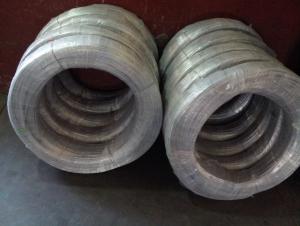
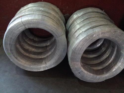
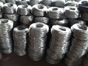
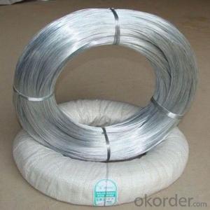
Electro Galvanized Wire:
Electro galvanized wire ranging from BWG8# to BWG16# is the mostly used for customers. We also offer thinner galvanized wire down to BWG5# or up to BWG28# upon customers specific order. Single coil package for electro galvanized wire can be as small as 10 kg and up to maximum 1000 kg per coil.
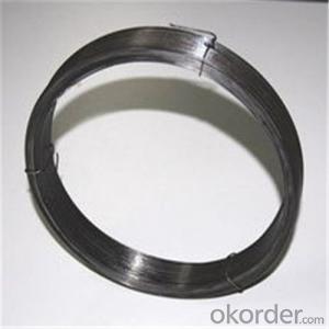
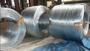
Electro Galvanized Wire Processing & Features:
This kind of galvanized wire is made with choice mild steel, through wire drawing, wire galvanizing and other processes. Electro galvanized wire has the characteristics of thick zinc coating, good corrosion resistance, firm zinc coating, etc.
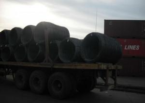
Forms of Supply:
Electro galvanized wire can be supplied in the form of coil wire, spool wire or further processed into straightened cut wire or U type wire.
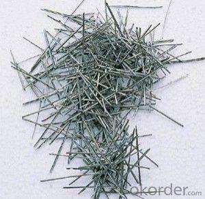
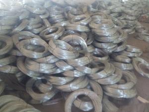
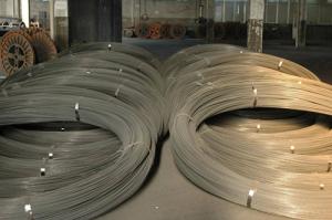
Electro galvanized wire applications:
Electro galvanized wire is mainly used in construction, express way fencing, binding of flowers and wire mesh weaving.
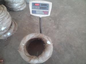
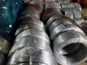
Electro galvanized iron wire, electro galvanized steel wire, electro galvanized wire.
BWG6-22 5.0MM-0.8MM.
Zinc coat: 5-25g/m2.
Tensile strength: 35-120kg/mm2.
ZINC COATING TABLE
SIZE mm | (g/㎡)Min. zinc coating | |||||||
A | AB | B | C | D | E | F | ||
A1 | B2 | |||||||
≤0.25 | 18 | 15 | 12 | 5 | ||||
〉0.25-0.40 | 25 | 20 | 12 | 5 | ||||
〉0.40-0.50 | 25 | 20 | 15 | 8 | ||||
〉0.50-0.60 | 25 | 20 | 15 | 8 | ||||
〉0.60-0.80 | 20 | 15 | 10 | |||||
〉0.80-1.20 | 25 | 18 | 10 | |||||
〉1.20-1.60 | 25 | 18 | 12 | |||||
〉1.60-1.80 | 100 | 70 | 40 | 30 | 20 | |||
〉1.80-2.20 | 105 | 80 | 50 | 40 | 20 | |||
〉2.20-2.50 | 110 | 80 | 55 | 40 | 25 | |||
〉2.50-3.00 | 120 | 90 | 70 | 45 | 25 | |||
〉3.00-4.00 | 100 | 85 | 60 | 30 | ||||
〉4.00-5.00 | 110 | 95 | 70 | 40 | ||||
- Q: I found an old Karavan flatbed utility trailer and am currently converting it into a snowmobile trailer (2 place). Me and a friend riped all the wire off of the trailer and completely rewired it. No matter how we configure it, the lights aren't coordinated. If we hit the left blinker in the car, all the lights flash(like the hazards are on). Right blinker works fine. we wired it first from the diagram on the karavan site. Now once we think about it, they have us wiring the ground into the light. so we searched the web and found this layout.
- The problem is the difference in 4 to 6 wire . Go to an auto parts store and get the converter . It wires into your car between the plug and the tail-lights .After that , no problem with older trailer wiring .
- Q: Im replacing the factory rear speakers in my car but cant figure on which wires are positive and which are negative. I went on a site for impalas but the color wires they have listed are not the same color wires in my car your help will be appreciated.
- Left Rear Speaker Positive Wire (+): Brown Left Rear Speaker Negative Wire (-): Yellow Right Rear Speaker Positive Wire (+): Dark Blue Right Rear Speaker Negative Wire (-): Light Blue
- Q: 01 F350 that did not come factory with cab lights.Bought the recon cab lights that come with its own harness. No plugs on the ends, just plain wires on the end. Where does the green wire splice in to behind the passenger kick panel?
- if a 2 wire loom, black is ground and green would be park lamps. get a test light, ground one end and stab wires until you find the live wire that lites the test lite. park lamp switch must be on when testing. head lamp switch 1 click out.
- Q: I just need to know what each wire is by the color because im trying to hook up my radio to it and the wires on it are different colors than the wires in my car i dnt kno wut is the ground/power/speaker wires or anything please help if you can. Thanks
- go to auto zone or wal-mart or advance auto parts and buy the wiring kit for your car. they have them for just about every car made these days. cost like 10-15 bucks, and is a simple install.
- Q: Broken dryer, 4 bladed wire, Old dryer available to me, has a 3 wire cord, can I swap the cords?
- Yes, download the owners manual, it will tell you how to the unground neutral, and use 4 wire cord, but generally you will just need to disconnect a jumper that connects the center terminal to ground, then connect the ground wire to the frame. Post the model number if you need help finding it. I am a little confused, it seems your first and second question are opposite, but doesn't matter, all dryers in North America can work with either type. The code says you have to use the 4 wire receptacle unless you only have three wires in the junction box. NEC 250.140 Frames of Ranges and Clothes Dryers Frames of electric ranges... shall be connected to the equipment grounding conductor... Exception: for existing branch-circuit installation only where an equipment grounding conductor is not present in the outlet or junction box, the frames of electric ranges...clothes dryers, and outlet or junction boxes that are part of the circuit for these appliances shall be permitted to be connected to the grounded circuit conductor... The Equipment grounding conductor is the green wire. The grounded circuit conductor is the white/neutral wire.
- Q: How do current carrying wires produce magnetism... Explain, give sites and clarify.
- dear any wire that having a moving charges (electrons) are having a magnetic field around this wire in loop and u can know the direction of the loops by the right hand role that if we cauch the wire in our right hand as the thumb pointing to the direction of the current then the other fingers which arounding the wire is pointing to the direction of the magnetic lines
- Q: I need thick floral wire and they keep saying things like 24 gauge 26 gauge 28 gauge.. like how would i know which one is thiickest if i'm buying it online.
- Floral Wire Gauge
- Q: What is a wire transfer? Is it when you can send money from one bank to another diferrent bank far away?
- You can also wire transfer to an individual. They initially were money oders and now are usually processed through an Automated Cleaing House Service (ACH).
- Q: i already tried wiring this light, but it didn't work. I always thought black wire to black, white to white and ground to ground. i connected the light fixture black wire to the three black wires (as shown in image) and the light fixture white wire to the three white wires, and connected ground wires together.when i flipped on the breaker, the light came on with the switch on off and the breaker tripped. i'm assuming this is wrong and i provided an image as i see in my ceiling mount. Can somebody kindly direct me how to properly connect the light fixture to these wires. thanks!
- This should have worked. Any chance you have one of the black wires touching the side of the box or one of the white or ground wires? If the fixture that was removed worked before the new one should work now. Also check that one of the screws holding the fixture didn't touch one of the black wires when you tightened it. .
- Q: Why is the current limiting circuit used to measure the resistance of wire by voltammetry?
- Under normal circumstances (to meet the safety conditions), because the current limiting circuit energy consumption is small, the connection is simple, therefore, priority is given to the current limiting method
Send your message to us
Electro Galvanized Wire BWG22 For Binding
- Ref Price:
-
- Loading Port:
- Tianjin
- Payment Terms:
- TT OR LC
- Min Order Qty:
- 5 m.t.
- Supply Capability:
- 1000 m.t./month
OKorder Service Pledge
OKorder Financial Service
Similar products

Hot products


Hot Searches
Related keywords

