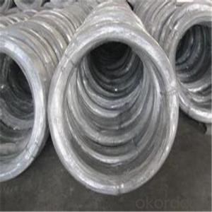

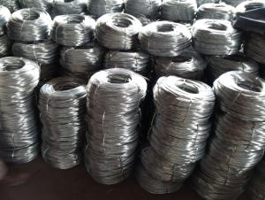
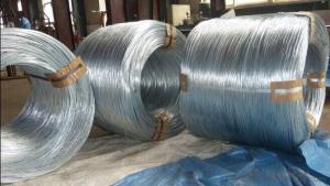
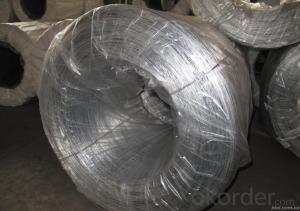
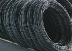
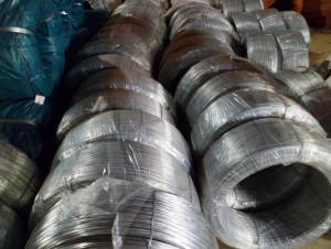
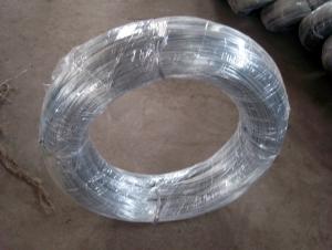
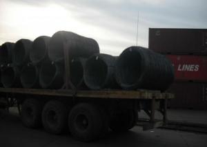
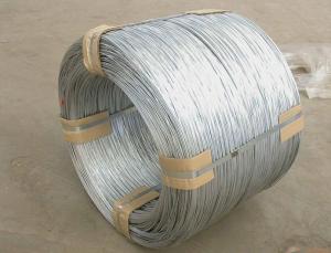
Electro Galvanized Steel Wires For Binding
- Ref Price:
-

- Loading Port:
- China Main Port
- Payment Terms:
- TT OR LC
- Min Order Qty:
- -
- Supply Capability:
- -
OKorder Service Pledge
OKorder Financial Service
You Might Also Like


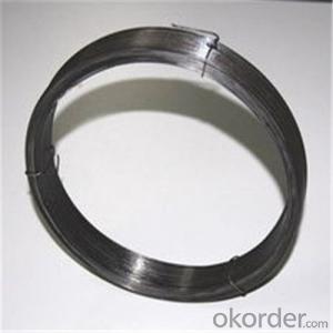


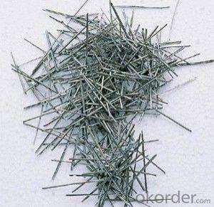
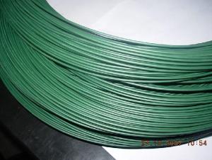
Galvanized Wire/Galvanized Steel Wire/ Gavanized Iron Wire
Diatmeters:0.15mm-6mm
Application | Weaving, braiding, fencing, cable armoring, knitting, tie wire, for redrawn, for binding or forming etc. |
Material | low carbon steel wire |
Diameter | 0.15mm~6.00mm |
Tensile strength | 350-500MPA, or higher |
Zinc coating | Min 12g/m2, min 25g/m2, min 200g/m2,min 300g/m2,610g/m2 |
Surface treatment | Hot dipped or electro galvanized |
Packing | On spools In small coils of 25-50kg/coil, 10kg/coil In rosette coil of 100-800kg/coil |
Standard | ASTM 641, EN10257-1& EN10244-2 |
All can be produced according to customers’ requirements.
- Q: wires have been cut and i have 4 wires i dont know what do.what colors are for what?
- What are you wiring??
- Q: Should I just buy normal speaker wire for wiring my subs together inside my box?? With positive and negative and then pull the wire apart and use only 1 of the wires? Also is 10 gauge good for this if my subs are 600 RMS a piece and my amp is 1180 birthsheet RMS...2 Kicker L5 12sAlpine PDX-1.1000
- well speaker wire inside the box i never would wire them together but 10 gauge sounds ok but just buy an amp wireing kit and it will give you proper wires just to be safe make sure all your wires can handel the power other wise it will burn the wires up yes you should pull the apart cause it wont sound right i usaly do is like the wires i buy have a white stripe on them i use that 1 as a ground wire so i know whic 1 is what
- Q: I notice my 10/100 Ethernet wire uses 4 wires (2 twisted pairs). I'm curious what each wire is used for. I understand one pair is for Tx (transmit) and the other for Rx (receive) but why does it need 2 wires for each? I assume bits of data cross on one, but what of the other?
- Your okorder /
- Q: I wanted to ask, im busy installing a new stereo headset for my car,when i replaced the old stereo with the new one, i used the wire harness from the old stereo and joint the wires to the back of new the stereo (which there is another black adapter that goes in the wire harness area on the the new stereo) i did this by connecting the wires from the stereo adapter to the wire harness that connects to the car, although the adapter that connects to the stereo has more wires than the wire harness that connects to the car,( i only connected the wires that were matching such as grey wire to grey wire, grey wire with black strip to grey wire with black strip, and so on, i obviously didn't connect the colours that didn't match to the wire harness wires, although i looked up online and apparently the yellow wire is a power wire, but i don't know where to connect it......if anyone could help, this would be greatly appreciated , i also wanted to ask, would this solve the problem if i buy a new wire harness? Thanks
- What kind of car is it? That's important, especially if it's a foreign make because those wires are so weird colored. Typically, yellow or ornage is power, red is memory, and the purple, gray, white, green wires are for the speakers .Black or brown wires are ground. Any blue wires you might come across are mainly just auxiliary signal wires that go to an aftermarket amp and subwoofer setup. Unless you have something like that, those wires can be taped off and forgotten about. Also, when wiring an aftermarket radio to your car, you will need to purchase an adapter harness that plugs into the stock wiring of the car and the wires connect to the radio wire harness correspondingly. I suggest soldering all the necessary wires and sealing them with shrink tube. It's the most solid, most sure way of a good connection without the worry of shorts and disconnections.
- Q: Hi I have a ceiling fan/light to put up but after taking down the original rose, I am now unsure how to wire the existing wiring into the ceiling fan the wiring is a s follows:block 1 Live empty,red,red, block 2 loop all empty, block 3 neutral empty,black,blackthe connections on the fan are live neutral and earthGrateful for any help
- Don't hurt yourself...Get someone with a volt meter to help you find which wire it what
- Q: first wire change
- Depends on how many little kinks he's putting in it. Also depends on how fast he works, if your wire needs a lot of work or a little, and if he already has an idea of what he wants to do or if he's just guessing along the way. It shouldn't take longer for him to make the actual kinks than it does the remove and replace the wire. That's a little more labor intensive and can take about 5-10 minutes for each wire. The whole thing, uninterrupted might last 30-45 minutes.
- Q: I'm trying to fix a light fixture for a friend. Her father-in-law gummed it up. At the fixture, there are 3 white wires soldered to a single wire. There are 3 black individual wires and one red wire. There are three switches that control the light.If I hook one of the black and the 3 white to the light, the light stays on constantly. If I hook either of the two other black individually, nothing comes on period.I'm pretty much at a loss. Any advice would be greatly appreciated.
- USA Sounds to me that what you have is 1 two conductor (black/white) cable as a power feed, 1 two conductor tap taking power somewhere else, and 1 three conductor (black, white, red) taking power to and back from a switch. All the whites get joined together, with a pigtail to the light. Make sure you have a tester. Find the black wire that is always energized, and mark it. Find the black and red that are in the same cable; mark them. I think what you have is they ran power to the light instead of the switch, then took the power down to the switch on the black conductor, and back from the switch to the light on the red conductor. Take the black that is always hot, and splice it to the other two blacks. Do not take it to the light. Hook the red to the light. If this does not work, reverse the red and black that go to the switch. This will take power to the switch on the red, and back from the switch on the black.
- Q: what are the limitations of international wire transfer
- Your bank may set a limit on the amount they will allow per wire transfer, but that would be the only limit. My company accepts wire transfers for international business almost daily and there have been a couple of time when I have had to have the purchasing company send a 2nd wire for the balance because the 1st exceeded the banks allowable transfer amount. Of course when that happens you have to be sure that you include the mark up to the customer invoice because you will be charges for each wire transfer by your bank. (some banks don't charge for incoming wires, some do.)
- Q: Say you have a 5 cm current wire carrying 10 A going from left to right. Directly 1 c.m below the left end of this wire is a long wire that is perpendicular to the first wire and goes out of the page. What is the net force on the 5 cm wire?I've tried using F=ILB with the I of the first wire and the B of the second wire.
- I didn't read the question so I was carefully working out the force. The wire is perpendicular to the first wire, so using the right hand rule you discover that the field it creates is PARALLEL to the first wire at this left end. The magnetic force is caused by the component which is PERPENDICULAR to the wire which is in fact zero. So there is no magnetic force at this point. As you move along the wire you get a diminishing amount of magnetism caused by the wire which is going out of the page but that field has a component which is DOWN the page. Therefore that part of the wire experiences a force which is into the page. ( take your right hand, put the thumb along the wire pointing to the right, the fingers point down the page, the palm points into the page which is then the direction of the force) I would be surprised if you were required to work out the magnitude of the force in this context. You can't use F= ILB because both the magnitude and the direction of the field varies at different points along the wire. If the perpendicular wire had been directly below the middle of the other wire there would have been no net force. If you were of a level where working out the force was appropriate you would need to set up the formula for B at various points along the wire, taking the vertical component only and integrate this over the range from 0 to 5 cm. Not a trivial mathematical task.
- Q: My home is wired for the thermostats with two wires (red and white). I have acquired a new thermostat that requires a Red, White, and Common wire. Using the white wire in that position will power the unit up but it won't trigger the heat. Is there something that can be put in line that will allow this thermostat to work without rewiring the house?
- Connect a new piece of 3 wire to the existing 2 wire and pull it through the wall by pulling the 2 wire. Of course if it gets stuck you will need to measure how far you pulled to know where to cut a hole in the wall. Cutting a hole in the wall if needed, isn't a big deal you just put the piece back, screw or nail it down (cut so you have studs on both sides to reattach it later) tape and plaster and paint.
Send your message to us
Electro Galvanized Steel Wires For Binding
- Ref Price:
-
- Loading Port:
- China Main Port
- Payment Terms:
- TT OR LC
- Min Order Qty:
- -
- Supply Capability:
- -
OKorder Service Pledge
OKorder Financial Service
Similar products


Hot products
Hot Searches
Related keywords

