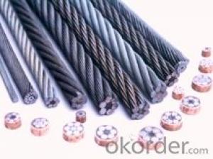
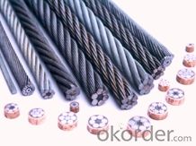
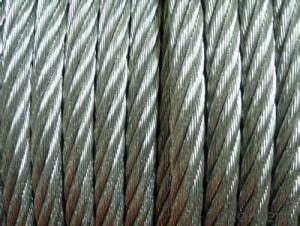
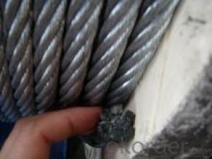
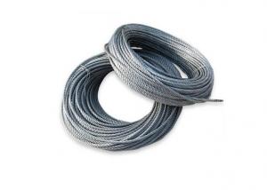
Steel wire rope of 6*19
- Ref Price:
-

- Loading Port:
- China Main Port
- Payment Terms:
- TT OR LC
- Min Order Qty:
- -
- Supply Capability:
- 20000 m.t./month
OKorder Service Pledge
OKorder Financial Service
You Might Also Like


Quick Details
Steel Grade:Q195 Q235 45# 60# 65# 70# 80# 82B carbon steel
Standard:AISI, ASTM, BS, DIN, GB, JIS
Wire Gauge:15.5mm
Place of Origin:Zhejiang, China (Mainland)
Type:steel wire rope
Application:fishing
Alloy Or Not:Non-alloy
Model Number:6x19
Zinc coating:it depends on the single wire diameter
Tensile strength:it depends on the single wire diameter
Packaging & Delivery
| Packaging Details: | wooden reel packing iron wooden reel packing |
|---|---|
| Delivery Detail: | it depends on the quantity of the order |
Specifications
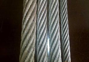
6*19 Steel wire rope
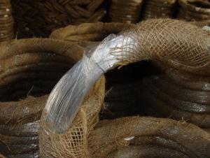
covering plastics for strands or ropes
configuration: GS3x24 GS3x19 SS6x19 SS6x24
diameter:3.0-9.6mm
Steel wire ropes
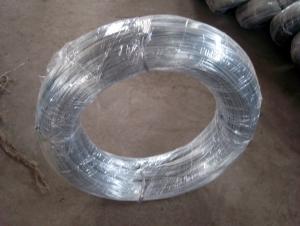
It might be widely used in the marine trawl fishing , and is also suitable for guardrail facilities such as the expressway, forest Park,etc. This products have Several advantages such as wear-resisting, long Duration , beautiful appearance. It is the improved products of the zinc coated wire, especially ues for offshore
- Q: I am changing an outside light with a inside wall switch there is 2 cables going to the outside box. ( 3 wires -white w/red line wire and black wire and green ground wire ) other cable 3 wires is white wire and black wire and green ground wire.On the inside switch is 3 wires white wire a black wire a green ground wire.for some reason it is not working, can any one tell me how to wire and or test for power. thank you
- Sounds like, cable #1 is coming from the Service Panel. The white ( with red line?) is the Neutral and connects to the white wire coming from the light fixture. The black is the Hot and connects to the black of the other cable set. The grounds all connect together and a pig tail should be fastened to the box if it is metal. The white wire from the other cable set should have black tape wrapped around the end to re-identify it as Hot and it should connect to the black wire coming from the light fixture. At the switch, connect the black to one terminal and wrap black tape on the white wire end and connect it to the other terminal. The ground should connect to the green ground terminal and if it has a metal box,pig tail to that.
- Q: i have just got a radio from a 2004dodge durango my buddy bought a new radio and i tok his old one, so now i need the wiring diagram to find out what all the wires goo too their are way more wires on thios thing that im use to on stock radios. ive looked it up online and its not the right diagrams the colors dont match up on the wires. ny help pleaseeee
- check out the link this is where i always go and always im able to find the car listing im looking for goodluck!
- Q: Need wiring diagram for ford F250 2004 disel
- hit okorder
- Q: I keep trying to strip this damned wire but the copper wire inside the tubeing constantly ends up getting split apart instead of staying together. Im pretty sure Im doing it right Ive done it before easily. The wire is very old though could that be the problem?
- Grab wire, and twist until it's back together, problem solved.
- Q: Obviously speaker wire is what connects the speaker to the receiver; what's the difference between 'zip' speaker wire and...others...?
- Zip okorder /
- Q: I have two low voltage wires that run from one side of a building to another. The insulation on both wires is the same color. I eventually just walked an additional wire around the building and checked continuity. Is there an easier way to differentiate between the two wires?
- 1. At one side of the building mark the two wires. 2. Connect a battery to the two ends noting which is positive. 3. Go to the other side of the building and use your voltmeter to determine which wire end is positive. Mark that one the sameas you did the other end of the positive wire.
- Q: I connected my wires in the morning and something aint righti put two wires incorrect but i dont see it... can some oneput them together for me cuz i really cant see where i did wrongmaybe some one else will find it ...
- Radio Constant 12V+ Wire: Yellow/Green == 5 Radio Switched 12V+ Wire: Purple == 4 Radio Ground Wire: Chassis == 6 Radio Illumination Wire: Red/Blue == NON Antenna Trigger Wire: Green/White == Antenna Power Antenna Wire: Green == 2 Front Speaker Size: n/a Front Speaker Location: n/a Left Front Speaker Wire (+): Blue/White == 16 Left Front Speaker Wire (-): Blue/Red == 15 Right Front Speaker Wire (+): White/Black == 9 Right Front Speaker Wire (-): Blue/Black == 10 Rear Speaker Size: n/a Rear Speaker Location: n/a Left Rear Speaker Wire (+): Green/Yellow == 13 Left Rear Speaker Wire (-): Black/Yellow == 14 Right Rear Speaker Wire (+): Blue == 12 Right Rear Speaker Wire (-): Red == 11
- Q: cat chewed two wires computer speaker wireand wii sensor bar wire well i can't just buy new ones or replace the wire so i need to reconnect them some how using insulated ferrules and electric tape and wire strippers any suggestions how to do this properly do i crimp them together with insulated ferrules or solder them together?what else can i do?i'm clueless how this worksneed help
- A temporary fix would be to strip about 1/2 to 3/8 inch of insulation off each wire and twist appropriate wires together and fasten with wire nuts. A permanent fix would be to strip and twist then solder then cover with electrical tape and only electrical tape, no duct or masking tape.
- Q: Will you please remove any of the wires? The edge of the body, which is made of wire or what? Is it copper or iron?
- Residential electrical wiring generally uses only one layer of plastic insulated copper core wire, which is usually worn in plastic pipes or steel tubes, concealed in the wall, in order to avoid mechanical damage. Conductor part of the conductor in the structure of solid and twisted two kinds, and its components are pure metal, alloy, coating and enameled wire. (referring to the Baidu encyclopedia wire structure) metals cannot ignite, and copper has a melting point of more than 1000 degrees! No electricity, no electricity, of course. Does not rub with wood to produce electricity or sparks.
- Q: Okay I bought a new light for outside my home. I called the electrician, he got the wiring from the ground and we added cement so we would bolt down the light. Now i need help adding a photocontrol.
- yes, the photo cell will work anywhere, in fact it will probably work better where the light is not hitting it when it comes on. It will work longer if direct sunlight cannot get at it.
Send your message to us
Steel wire rope of 6*19
- Ref Price:
-
- Loading Port:
- China Main Port
- Payment Terms:
- TT OR LC
- Min Order Qty:
- -
- Supply Capability:
- 20000 m.t./month
OKorder Service Pledge
OKorder Financial Service
Similar products

Hot products

Hot Searches
Related keywords

