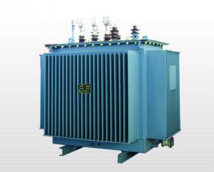
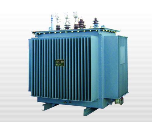
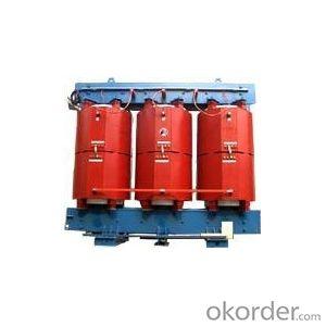
SCB9-30-2500-10 Epoxy resin dry-type power transformer
- Ref Price:
-

- Loading Port:
- Shanghai
- Payment Terms:
- TT OR LC
- Min Order Qty:
- -
- Supply Capability:
- 1000sets set/month
OKorder Service Pledge
OKorder Financial Service
You Might Also Like
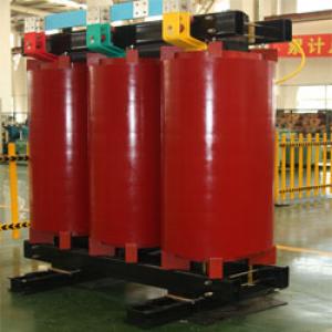


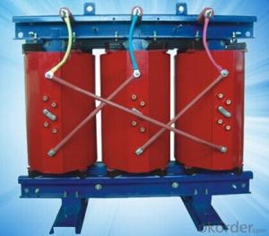
Production introduction
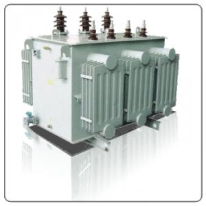
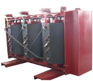
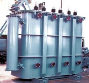
The dry-type transformers are casted with epoxyresin,which are made of high quality materials by means of a strict process with advanced production and testing devices.The product features high reliability and long service life.In accordance with different operation environment,it can be equipped with different protection casings or without casing.It can replace the oil-immersed transformer and be used in the high buildings,business centers,airports,tunnels,chemical plants,nuclear power stations and watercrafts ect.
Normal service conditions
1)Altitude should not be over 1000m:indoor type
2)Highest ambient temperature should not over:+40oC;Highest daily average should not over temperature:+30oC
3)Highest annual average temperature should not over +20oC,lowest temperature should not below -5oC.We can provide transformer operated in special conditions according to user's requirement.
Model designation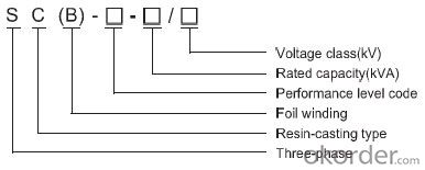
Applicable standards
GB6450-1986 Dry-type power transformer
GB4208-1993 Casing protection grade(IP code)
GB/T10228-1997 Technical parameters and requirements for dry-type power transformer
Performance characteristics
1.The product is safe,fire-proof,pollution free,and can be used in the load center directly.
2.High mechanical strength,strong shour-circuit proof capacity,small partial discharge,excellent thermal stability,high reliability,and long service life.
3.Low loss,low noise,energy saving and maintenance free.
4.Excellent heat dissipation,great overload capacity and a large operating capacity is available when ONAF is applied.
5.Good humidity resistance,it's suitable for operating in the highly humid and harsh environment.
6.An intelligent signal and temperature control system is adopted,which can automatically monitor and display all working temperature of the three-phase windings.The blowing fan can give an alarm,switch on and off automatically and conduct tripping operation to protect the transformer.
7.Dur to the structure is compact and weight is light,it can save space and decrease the cost of installation.
Notes for placing orders
Transformer type:rated capacity kVA
Number of phases:three-phase single-phase
High voltage: KV/Low voltage:KV
Frequency:50HZ 60HZ
Tapping range:±4×2.5% ±3×2.5% other
Connection group:Yyn0 Dyn11 other
Impedance voltage:4% 6% other
Cooling method: ONAN ONAF
Protecting grade of outer casing:IP00 IP20 IP30 other
Method of incoming and outgoing line:
1.Incoming line to lower part and outgoing line from upper part
2.Incoming line to upper part and outgoing line form upper part
3.Incoming line to upper part and outgoing line form side part
- Q: What is the transformer through the full and half through the problem, the definition of a little more, the best reference, or sent to my literature.
- Dual split transformer compared with the general power transformer, there are four important impedance parameters: (1) through the impedance: two low-voltage winding in parallel, the high and low voltage winding short-circuit impedance, that is, high-voltage winding short circuit, two low-voltage winding in parallel after adding the current equivalent impedance. Where the reactance component is referred to as crossing the reactance. (2) half-crossing impedance: one of the two low-voltage windings open, the other low-voltage winding between the high-voltage winding short-circuit impedance, that is, high-voltage winding short circuit, a low-voltage winding open, and the other does not open the low-voltage winding power Value impedance. Where the reactance component is called a half-pass reactance.
- Q: I have a transformer which I got from a alarm system and wondered if I can use it in conjunction with my newly purchased bread board.I don't know how I would tell what the transformer is, I'm assuming the input is 230v (UK) but the output I'm not sure. The resistances of the windings are 0.7 ohms and 74 ohms. I'm assuming the output will be around 23V? Also, if I was to use this, which winding would the mains connect to, the lower resistance or higher resistance?
- If it is a mains transformer, then the primary and secondary windings will be on separate bobbin sections with an insulator between them. The higher resistance winding will be the primary (mains) winding, as it has more turns than the secondary and is made of thinner wire. (Resistance tests on a transformer are not generally very informative as most meters measure only the DC resistance, and transformers behave quite differently when supplied with AC.) The easiest way to find out what comes out of the secondary winding, is to apply power to the primary. That will give you the off-load voltage. To find out how much current you can safely draw, you will need to measure the temperature of the transformer under load. It's safe if it isn't too hot to touch the laminations (at the furthest point away from the mains terminals, obviously) with your bare hands.
- Q: Rectifier and rectifier transformer
- The rectifier is a device that turns AC into a DC. Rectifier transformer is to provide the rectifier with the corresponding AC input power. Rectifier transformer is done AC / AC conversion, and rectifier is done AC / DC conversion.
- Q: A step up transformer has 5,000 turns in the secondary coil and 200 turns in the primary coil. The primary is supplied with alternating current with an effective voltage of 900V. (A) What is the voltage in the secondary coil? (B) If the current in the secondary coil is 20A, what current flows in the primary coil? (C) What power is developed in the primary coil? (D) What power is developed in the secondary coil?
- A step up transformer has 5,000 turns in the secondary coil and 200 turns in the primary coil. N1 200 turns N2 5000 turns The primary is supplied with alternating current with an effective voltage of 900V. V1 900V (A) V2 ? V2 N2 / N1 x V1 V2 5000 / 200 x 900 25 x 900 22,500V (B) I2 20A ; I1 ? V1 x I1 V2 x I2 I1 (V2 x I2) / V1 I1 (22500V x 20A) / 900V I1 500 A (C) P1 ? P1 V1 x I1 P1 900V x 500A 450,000W (D) P2 ? P2 V2 x I2 P2 22,500V x 20A 450,000W Yep, the power in the primary is equal to power in the secondary.
- Q: Branch circuit cables are rated for 75?C and feeder cables are rated for90°C. This will be a 3-phase, 575-volt system with four induction motors, specified asfollows:Motor 1: 60 hp 0.90 p.f. squirrel cage motorMotor 2: 60 hp 0.90 p.f. squirrel cage motorMotor 3: 40 hp 0.85 p.f. wound rotor motorMotor 4: 7-1/2 hp 0.80 p.f. wound rotor motorA) Assuming no line losses, find the capacity of the transformer required to supplypower to this system.B) Assume that it is desired to improve the overall power factor for this system to 0.95lagging. Determine, in kVAR, the required capacitance for this power factorcorrection.C) Assume these motors have their windings connected in a delta configuration. Whatwould be the line voltage if they were connected in wye?
- I would look in the NEC for the full load amperes of these motor sizes. These are: 7.5 HP9 amps 40 HP.41 amps 60 HP.62 amps The 7.5 HP motor KVA will be KVA 575 * 9 * 1.732 8.9631 The 7.5 HP motor KW will be KW 575 * 9 * 1.732 * 0.8 7.17048 The KVAR of this motor is Sqrt(8.9631^2 - 7.1705^2) 5.3778 The 40 HP motor KVA will be KVA 575 * 41 * 1.732 40.8319 The 40 HP motor KW will be KW 575 *41 * 1.732 * 0.8 5 34.707115 The KVAR for this motor is Sqrt(40.8319^2 - 34.7071^2) 21.5095 The 60 HP motor KVA will be KVA 575 * 62 * 1.732 61.7458 The 60 HP motor KW will be KW 575 *62 * 1.732 * 0.8 5 55.5712 The KVAR for this motor is Sqrt(61.7458^2 - 55.5712^2) 26.9141 The total KVA requirement for all motors running at once is 8.9631 + 40.8319 + 61.7458 + 61.7458, which is 173.2866 KVA (note this is the requirement from a transformer, not the size of the transformer The total KW of all the motors is 7.1701 + 34.7071 + 55.5712 + 55.5712 153.0196 KW The total KVAR of all the motors is 5.3778 + 21,5095 + 26,9141 + 26.9141 80.7145 KVAR The power factor for all the motor is KW / KVA 153.0196 / 173.2866 0.883 I took a short cut at this point and used an application i wrote to calculate the required capacitor KVAR. The results follows: At 0.95 power factor, the motors' KVA will be 161.065 The motors' KW will be the same. The motors' KVAR will be 50.2926 The required capacitor's KVAR will be 53.988 The reactance of the capacitor will be 10.65 ohms The capacitance will be 3.49059248 E -4 Farads You can calculate these values as I did above, if you want to. EDIT Forgot the last answer. The line voltage is the same for both delta and wye. The leg voltage for the wye motor will be 575 / 1.732 331.98 volts TexMav
- Q: I have a US Navy Plate and Filament Transformer Manufactured by Hudson American Corporation.This monster weighs 14.5lbs, and is in a sealed steel casing.There are 16 unlabeled terminals, and I'm working to identify those.It does however have the current and voltage labelings for the primary and secondaryPrimary : 110/115/120v AC (Since there are 16 taps, I'm guessing that these are separate primaries)Secondary 1:360-0-360 200MA DCSecondary 2: 6.6v 10A CTSecondary 3: 12.6V 3ASecondary 4: 5.25V 3AI'm set on using a solid state rectifier circuit so i don't need the 5.25V Line, or the 12.6V line.Could I somehow do something to get extra current on the B+ line (S1 windings) with these unused secondaries?I want 4x 6550/kt88, so the extra plate current would be great to have around.
- You can probably draw a bit more from the 720 volt winding if you don't use some of the other windings. Also if you use SS rectifiers, you will get more DC voltage than normal, about 490-500 volts, so the extra drop you would get at higher current may be ok. Or you could use a choke input filter instead of a cap input to get about 350 volts, enough to operate KT88's, and get more current. Watch out for over heating. edit: Electrolytic caps would be a lot smaller than the ones you have. The two chokes in parallel could be used as a choke input filter. Exactly what voltage and current do you need?
- Q: I understand that a 70-volt transformer is used in a commercial environment, to connect several 70-volt speakers to a 70-volt amplifier. But why does a 70-volt transformer have all of those different colored wires coming from it? What do they connect to, and what are they for? How would I connect a 70-volt transformer to an amplifier, and where I connect the cable that goes to the speakers? Please explain this to me in an easy to understand way, because I was curious about this for a long time.
- The okorder
- Q: I feel that Transformers was because that sh*t was hot! And Shia LaBeouf was pretty HOTT too!
- Simple, TRANSFORMERS rocks. Well, you can call me nuts! It was so goood, I watched it SIX times. To me, Transformers just broke the barrier when it comes to making robots that interact well with humans. The awesomely human-like behaviour of the Autobots, the cool action scenes, fast but cool transformations and the god-like Optimus Prime took my breathe away! Absolutely the best movie this year. No one could ask for a better live adaptation of a cartoon, especially one that we used to love.
- Q: I just purchased a little halogen spotlight lamp with an Class II transformer that converts 110v-120V to 11.5V. When I put my ears about a 12 inches from the transformer near the wall outlet, I hear a little buzzing or humming noise. Is this normal or is there something wrong?
- A transformer creates a magnetic field that varies at the rate of the line voltage (60 or 50 cycles per second). If there is something in that field that is magnetic, it will be pushed back and forth at that rate, and if it can move, it will create a buzzing sound. Almost all transformers produce a little bit of sound, because the core is made up of layers of magnetic material that are glued together. It's not anything to worry about, just a nuisance.
Send your message to us
SCB9-30-2500-10 Epoxy resin dry-type power transformer
- Ref Price:
-
- Loading Port:
- Shanghai
- Payment Terms:
- TT OR LC
- Min Order Qty:
- -
- Supply Capability:
- 1000sets set/month
OKorder Service Pledge
OKorder Financial Service
Similar products


Hot products


Hot Searches
Related keywords

