
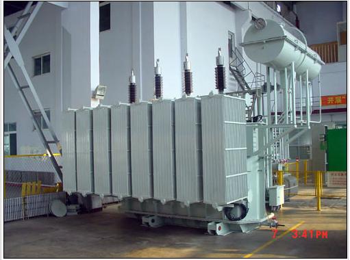
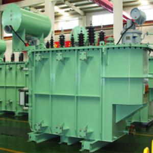
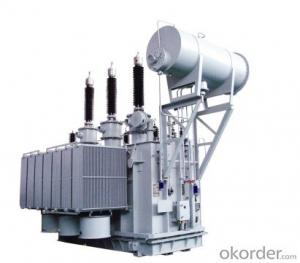
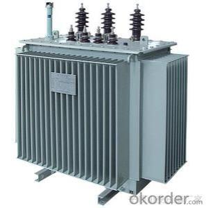
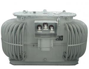
Oil immersed Power Transformer 66kV
- Ref Price:
-

- Loading Port:
- China Main Port
- Payment Terms:
- TT OR LC
- Min Order Qty:
- -
- Supply Capability:
- -
OKorder Service Pledge
OKorder Financial Service
You Might Also Like


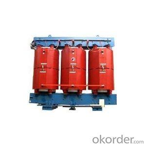
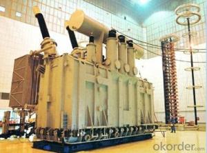
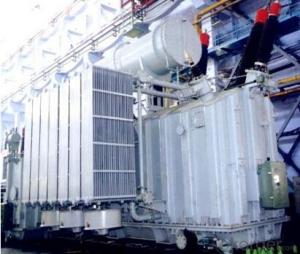
66kV Oil-immersed Power Transformers

1. Productintroduction
Oil immersedpower transformers designed and manufactured by us is based on advanced technologiesand rich experiences. The products have been improved in the design, structureand processes, with good resistance to short circuit capacity, good mechanicalproperties, lower partial discharge, low noise, no leakage, beautifulappearance, easy maintenance etc.
2. Workingcondition
Altitude: <1000M ( can be adjusted according to customer requirements)
Maximum environmental temperature: +40 ℃, Minimum environmental temperature: -40 ℃ (can be adjusted upon customer’s request)
Maximum wind speed: 36.2m / s
Relative humidity: 90%
Earthquake intensity: seismic acceleration (horizontal and vertical component take effectsame time) transformer can withstand seismic forces of 8 Richter scale earthquake.
Contaminationlevel: 3
3. Standards
GB1094.1Power Transformer General Regulation
GB1094.2Power Transformer Temperature rise
GB1094.3Power Transformer Insulation Levels andInsulation Tests
GB1094.5Power Transformers Short-circuit Capacity
GB6451 Oil-immersed power transformerstechnical parameters and requirements
4. Model Description
 ‘
‘
5. Technical parameter for 66kV Three-phase power transformers
S9 type 630kVA-63000kVA no excitation Voltage-regulationthree-phase double-winding power transformer
Code | Rate capacity kVA | Voltage combination and Sub-connection range | Connection Type Symbol | No Load Loss kW | Load Loss kW | No Load Current % | Short Circuit impedance % | Weight kg | Dimension mm | ||||||
HV kV | HV sub- connection range% | LV kV | Body | Oil | Total | L | W | H | |||||||
S9-630/66 | 630 | 63 66 69 | ±5 | 6.3 6.6 10.5 11 | Yd11 | 1.6 | 7.5 | 1.40 | 8 | 1660 | 1600 | 4650 | 2100 | 1800 | 3010 |
S9-800/66 | 800 | 1.9 | 9.0 | 1.35 | 1950 | 1660 | 4700 | 2150 | 1830 | 3030 | |||||
S9-1000/66 | 1000 | 2.2 | 10.4 | 1.30 | 2180 | 2000 | 5800 | 2340 | 1850 | 3150 | |||||
S9-1250/66 | 1250 | 2.6 | 12.6 | 1.30 | 2500 | 2100 | 5900 | 2350 | 1880 | 3200 | |||||
S9-1600/66 | 1600 | 3.1 | 14.8 | 1.25 | 2740 | 2600 | 7200 | 2500 | 1900 | 3400 | |||||
S9-2000/66 | 2000 | 3.6 | 17.5 | 1.20 | 3130 | 2730 | 7680 | 2530 | 1950 | 3450 | |||||
S9-2500/66 | 2500 | 4.3 | 20.7 | 1.10 | 3570 | 2880 | 7800 | 2550 | 2280 | 3550 | |||||
S9-3150/66 | 3150 | YNd11 | 5.1 | 24.3 | 1.05 | 4210 | 3050 | 7950 | 2620 | 2330 | 3650 | ||||
S9-4000/66 | 4000 | 6.0 | 28.8 | 1.00 | 4750 | 3200 | 10750 | 2650 | 2630 | 3890 | |||||
S9-5000/66 | 5000 | 7.2 | 32.4 | 0.85 | 5290 | 3630 | 12000 | 2900 | 3000 | 3900 | |||||
S9-6300/66 | 6300 | 63 66 69 | ±2x2.5 | 6.3 6.6 10.5 11 | 9.2 | 36.0 | 0.75 | 9 | 7540 | 4200 | 15200 | 3200 | 3050 | 4000 | |
S9-8000/66 | 8000 | 11.2 | 42.7 | 0.75 | 9940 | 5750 | 21100 | 4550 | 3500 | 4350 | |||||
S9-10000/66 | 10000 | 13.2 | 50.4 | 0.70 | 11760 | 7450 | 24500 | 4600 | 3650 | 4400 | |||||
S9-12500/66 | 12500 | 15.6 | 59.8 | 0.70 | 14700 | 9800 | 26400 | 4800 | 3800 | 4500 | |||||
S9-16000/66 | 16000 | 18.8 | 73.5 | 0.65 | 17830 | 9860 | 33800 | 5500 | 3900 | 4580 | |||||
S9-20000/66 | 20000 | 22.0 | 89.1 | 0.65 | 21510 | 6650 | 39200 | 5600 | 3950 | 4880 | |||||
S9-25000/66 | 25000 | 26.0 | 105.3 | 0.60 | 24500 | 11230 | 44100 | 5750 | 4200 | 4950 | |||||
S9-31500/66 | 31500 | 30.8 | 126.9 | 0.55 | 27440 | 12550 | 49000 | 6300 | 4650 | 5000 | |||||
S9-40000/66 | 40000 | 36.8 | 148.9 | 0.55 | 29400 | 14500 | 53900 | 6530 | 4700 | 5100 | |||||
S9-50000/66 | 50000 | 44.0 | 184.5 | 0.50 | 32530 | 16800 | 58800 | 6800 | 4750 | 5200 | |||||
S9-63000/66 | 63000 | 52.0 | 222.3 | 0.45 | 38000 | 17000 | 63800 | 7300 | 4850 | 5250 | |||||
Note:
1. Weightand dimensions are for reference only, may vary depending on user needs.
2. Providetype 10 or type 11 loss products as customer’s demand.
3. Provideself-cooling or air-cooling as customer’s demand.
SZ9 type 6300kVA-63000kVA OLTCthree-phase double-winding power transformer
Code | Rate capacity kVA | Voltage combination and Sub-connection range | Connection Type Symbol | No Load Loss kW | Load Loss kW | No Load Current % | Short Circuit impedance % | Weight kg | Dimension mm | ||||||
HV kV | HV sub- connection range% | LV kV | Body | Oil | Total | L | W | H | |||||||
SZ9-6300 | 6300 | 63 66 69 | ±8x1.25 | 6.3 6.6 10.5 11 | Ynd11 | 10.0 | 36.0 | 0.75 | 9 | 7550 | 4180 | 15200 | 3200 | 3050 | 4000 |
SZ9-8000 | 8000 | 12.0 | 42.7 | 0.75 | 10020 | 5750 | 21100 | 4550 | 3830 | 4350 | |||||
SZ9-10000 | 10000 | 14.2 | 50.4 | 0.70 | 11700 | 7450 | 24500 | 4600 | 3650 | 4150 | |||||
SZ9-12500 | 12500 | 16.8 | 59.8 | 0.70 | 14650 | 9800 | 26500 | 4200 | 3800 | 4850 | |||||
SZ9-16000 | 16000 | 20.2 | 73.5 | 0.65 | 17850 | 9750 | 33500 | 5500 | 4000 | 4450 | |||||
SZ9-20000 | 20000 | 24.0 | 89.1 | 0.65 | 21540 | 9980 | 39200 | 5600 | 4000 | 5100 | |||||
SZ9-25000 | 25000 | 28.4 | 105.3 | 0.60 | 24500 | 11230 | 44100 | 5750 | 4300 | 4750 | |||||
SZ9-31500 | 31500 | 33.7 | 126.9 | 0.55 | 27450 | 12560 | 49000 | 6300 | 4650 | 4850 | |||||
SZ9-40000 | 40000 | 40.3 | 148.9 | 0.55 | 29400 | 14400 | 53800 | 6500 | 4700 | 5100 | |||||
SZ9-50000 | 50000 | 47.6 | 184.5 | 0.50 | 32530 | 16700 | 58800 | 6800 | 4700 | 5200 | |||||
SZ9-63000 | 63000 | 56.2 | 222.3 | 0.45 | 38000 | 17150 | 64500 | 7300 | 4850 | 5250 | |||||
Note
1. Weightand dimensions are for reference only, may vary depending on user needs.
2. Providetype 10 or type 11 loss products as customer’s demand.
3. Provideself-cooling or air-cooling as customer’s demand.
S11 type 630kVA-63000kVA no excitationVoltage-regulation three-phase double-winding power transformer
Code | Rate capacity kVA | Voltage combination and Sub-connection range | Connection Type Symbol | No- Load Loss kW | Load Loss kW | No Load Current % | Short Circuit impedance % | Weight kg | Dimension mm | ||||||
HV kV | HV sub- connection range% | LV kV | Body | Oil | Total | L | W | H | |||||||
S11-630/66 | 630 | 63 66 69 | ±5 | 6.3 6.6 10.5 11 | Yd11 | 1.3 | 7.1 | 1.40 | 8 | 1700 | 1680 | 4750 | 2100 | 1800 | 3050 |
S11-800/66 | 800 | 1.5 | 8.5 | 1.35 | 1750 | 1750 | 4860 | 2200 | 1800 | 3070 | |||||
S11-1000/66 | 1000 | 1.8 | 9.8 | 1.30 | 2230 | 2100 | 6000 | 2400 | 1850 | 3100 | |||||
S11-1250/66 | 1250 | 2.1 | 11.9 | 1.30 | 2350 | 2270 | 6500 | 2460 | 1860 | 3170 | |||||
S11-1600/66 | 1600 | 2.5 | 14.0 | 1.25 | 2800 | 2700 | 7500 | 2500 | 1900 | 3400 | |||||
S11-2000/66 | 2000 | 2.9 | 16.6 | 1.20 | 3200 | 2750 | 7850 | 2550 | 2250 | 3500 | |||||
S11-2500/66 | 2500 | 3.4 | 19.6 | 1.10 | 3650 | 2950 | 8150 | 2600 | 2280 | 3580 | |||||
S11-3150/66 | 3150 | YNd11 | 4.1 | 23.0 | 1.05 | 4300 | 3100 | 9950 | 2630 | 2330 | 3650 | ||||
S11-4000/66 | 4000 | 4.8 | 27.3 | 1.00 | 4850 | 3180 | 11000 | 2680 | 2630 | 3900 | |||||
S11-5000/66 | 5000 | 5.8 | 30.7 | 0.85 | 5400 | 3700 | 12200 | 2950 | 3000 | 3900 | |||||
S11-6300/66 | 6300 | 63 66 69 | ±2x2.5 | 6.3 6.6 10.5 11 | 7.4 | 34.2 | 0.75 | 9 | 7700 | 4280 | 15500 | 3200 | 3050 | 4000 | |
S11-8000/66 | 8000 | 8.9 | 40.5 | 0.75 | 10150 | 5850 | 21500 | 4550 | 3830 | 4350 | |||||
S11-10000/66 | 10000 | 10.5 | 47.8 | 0.70 | 12000 | 7600 | 25000 | 4600 | 3650 | 4150 | |||||
S11-12500/66 | 12500 | 12.5 | 56.8 | 0.70 | 15000 | 10000 | 27000 | 4800 | 3800 | 4350 | |||||
S11-16000/66 | 16000 | 15.0 | 69.8 | 0.65 | 18200 | 9900 | 34500 | 5500 | 4000 | 4450 | |||||
S11-20000/66 | 20000 | 17.6 | 84.6 | 0.65 | 21950 | 10150 | 40000 | 5600 | 4000 | 4620 | |||||
S11-25000/66 | 25000 | 20.8 | 100.5 | 0.60 | 25000 | 11450 | 45000 | 5750 | 4300 | 4750 | |||||
S11-31500/66 | 31500 | 24.6 | 120.5 | 0.55 | 28000 | 12800 | 50000 | 6300 | 4650 | 4850 | |||||
S11-40000/66 | 40000 | 29.4 | 141.4 | 0.55 | 30000 | 15000 | 55000 | 6500 | 4700 | 5100 | |||||
S11-50000/66 | 50000 | 35.2 | 175.2 | 0.50 | 33200 | 17000 | 60000 | 6800 | 4750 | 5200 | |||||
S11-63000/66 | 63000 | 41.6 | 2211 | 0.45 | 38800 | 17500 | 65000 | 7300 | 4850 | 5250 | |||||
S11type 6300kVA-63000kVA OLTC three-phase double-winding power transformer
Code | Rate capacity kVA | Voltage combination and Sub-connection range | Connection Type Symbol | No Load Loss kW | No Load Loss kW | No Load Current % | Short Circuit impedance % | Weight kg | Dimension mm | ||||||
HV kV | HV sub- connection range% | LV kV | Body | Oil | Total | L | W | H | |||||||
SZ11-6300/66 | 6300 | 63 66 69 | ±8x1.25 | 6.3 6.6 10.5 11 | Ynd11 | 8.0 | 34.2 | 0.75 | 9 | 7700 | 4280 | 15500 | 3200 | 3050 | 4000 |
SZ11-8000/66 | 8000 | 9.6 | 40.5 | 0.75 | 10150 | 5850 | 21500 | 4550 | 3800 | 4350 | |||||
SZ11-10000/66 | 10000 | 11.4 | 47.8 | 0.70 | 12000 | 7600 | 25000 | 4600 | 3650 | 4150 | |||||
SZ11-12500/66 | 12500 | 13.4 | 56.8 | 0.70 | 15000 | 10000 | 27000 | 4200 | 3800 | 4850 | |||||
SZ11-16000/66 | 16000 | 16.2 | 69.8 | 0.65 | 18200 | 9900 | 34500 | 5500 | 4000 | 4450 | |||||
SZ11-20000/66 | 20000 | 19.2 | 84.6 | 0.65 | 21950 | 10150 | 40000 | 5600 | 4000 | 5100 | |||||
SZ11-25000/66 | 25000 | 22.7 | 100.5 | 0.60 | 25000 | 11450 | 45000 | 5750 | 4300 | 4750 | |||||
SZ11-315000/66 | 31500 | 27 | 120.5 | 0.55 | 28000 | 12800 | 50000 | 6300 | 4650 | 4850 | |||||
SZ11-40000/66 | 40000 | 32.2 | 141.4 | 0.55 | 30000 | 15000 | 55000 | 6500 | 4700 | 5100 | |||||
SZ11-50000/66 | 50000 | 38.1 | 175.2 | 0.50 | 33200 | 17000 | 60000 | 6800 | 4700 | 5200 | |||||
SZ11-63000/66 | 63000 | 45 | 211.2 | 0.45 | 38800 | 17500 | 65000 | 7300 | 4850 | 5250 | |||||
- Q: I didn't. I even watched it at I-Max with my boyfriend and a few friendslets just say I wasn't the only one falling asleep. It was long, too long. They could have cut it down by at least 30 minutes.
- I agree with you. It was long and boring.
- Q: I have 13 lights with 12 volts 35 Watts on each light for each tree, the outlet is 120 volts current now. Should I buy 300Watt or 600Watt low volts transformer to supply all lights? Need your advise!
- 600 W.
- Q: I just saw the movie and it has left me with a thirst for more on the story of transformersbut where can I turnComics, animated series?Thanks
- Almost anywhere you go, you're going to get a slightly different story than what you got in the movie. If you really want something that fits in directly with the movie continuity, publisher IDW did a series of movie prequel comics which are probably available as a trade. For TV shows, the closest thing to what you saw in the movie is the original 1980's animated series, which is available on DVD. Beast Wars and Beast Machines both reference the 1980s cartoon (the former more than the latter) and Beast Wars at least is worth watching. Since then, there have been a number of largely terrible dubbed anime TransFormers shows airing in the US, which I would reccommend you skip. There are also a few shows that aired exclusively in Japan, of varying quality. And there's a new animated series coming out sometime next year which I think could be quite good. In terms of comics, you have the original Marvel series, some of which has been reprinted in trades, the Dreamwave series (which I personally did not care for), and the current IDW books, which I really enjoy. IDW covers a lot of different parts of the TransFormers mythos (G1, Beast Wars, movie, etc.) so you can pick what most interests you.
- Q: I live in Market Weighton and I need to know why my local electricity transformer is. Where will I need to look?
- For residential, the step down transformer for home electricity use is typically a pole top mounted transformer. It may be at the top of a power pole near your residence. Sometimes there may be a pad mount transformer (square metal box) near your home that is used. You may want to look outside your home, and see where the wires coming into your electrical service are coming from. That should tell you where the transformer is. If you live in a newer neighborhood, you may have underground service ( thus no power poles) and the transformer may not be visible. It would likely be close by in an underground electrical vault. There is a picture of a pole top transformer in the attached article below:
- Q: do you know when the knew transformers film is coming out ( the year as well)
- Transformers: Revenge of the Fallen (2009) Release Date: 24 June 2009 (UK) :] Hope this helped. I soo wana' see this movie.
- Q: i am recently watching transformers prime and i am a big fan of all transformers but now i am confused.i generation 1 and 2 was good then they ended.does transformers cybortron trilogy a sequel to g2 or new start and then is tranformers prime a sequel to transformers fall of cybortrons?
- 1) In the G1 timeline we have a sequel series made exclusively for Japanese audiences. They completely ignore the events in the American ending and go in a completely different direction. 1) Transformers: Headmasters 2) Transformers: Super-God Masterforce 3) Transformers: Victory 4) Transformers: Zone Then there's Beast Wars and Beast Machines is a sequel/prequel to the G1 series. ___________________________ 2) Transformers: Robots in Disguise (RiD) aka Transfomers: Car Robots in Japan is a complete standalone series, no relation to any other existing TF series ____________________________ 3) The Unicron Trilogy is it's own timeline that has 3 series. US - JP Armada - Micron Legend Energon - Superlink Cybertron - Galaxy Force but the 3rd series, Cybertron, was originally a self-contained series, the American version edits the dialogue to make it appear as a sequel to Armada and Energon. Also, the character Override, who is female in the US version, is male in the Japanese. In other words in Japan the first 2 are in the same continuity and the 3rd is a another reboot.
- Q: can any one give me a fast time line of transformers history
- The gods Primus and Unicron nearly destroy the universe fighting until Primus tricks Unicron by imprisoning them both in metal planetoids. Unicron becomes giant transforming world devourer and Primus becomes Cybertron, bringing to life the transformer race that will fight Unicron in his stead. The robots of Cybertron eventually begin civil war which go on for millions of years, the evil Decepticons vs the heroic Autobots. Unicron finds Cybertron, the Autobot leader destroys him with the Matrix, the transformers fulfill their destiny. Their war continues until Cybertron is nearly depleted so the planet is reformatted and the race adopt Maximal and Predacon castes. New wars begin until balance is struck and Cybertron becomes technorganic paradise
- Q: After the calculation, due to the different cooling, the current density is different, I finished a winding section 96.5mm ?, secondary winding section 1562.5mm ? What are the specifications of the copper row? Another request for a transformer copper specifications table.
- A general use of cable out, select 120mm2 line can be; second to use two 100 × 10mm copper, copper is to tin treatment. Copper specifications table recommended to find the national standard, see the copper discharge capacity and installation methods, after all, the transformer must be produced to meet the national standard.
- Q: I want to make presentation about transformers, I need to know suitable definition.I also want to know the Major Components, and Protection devices.Thanks a lot
- Watch Popular Movies Online
- Q: "A transformer ratio is 110/11, then it is" "A transformer ratio of 110 / 10.5, it is" "A transformer ratio of 121 / 10.5, it is"
- For example, 10KV system, the transformer primary winding rated voltage of 10KV and 10,5KV, secondary winding rated voltage of 10.5 and 11KV. 110KV system, the transformer primary winding rated voltage of 110KV, secondary winding rated voltage of 121KV. 220KV system, the transformer primary winding rated voltage of 220KV, secondary winding rated voltage of 242KV. and many more. 110KV is a winding, that is, 110 variable 10.5KV course is the buck variable. Secondary winding for the 121KV, that is, 10.5 variable 121KV course, the pressure has changed.
Send your message to us
Oil immersed Power Transformer 66kV
- Ref Price:
-
- Loading Port:
- China Main Port
- Payment Terms:
- TT OR LC
- Min Order Qty:
- -
- Supply Capability:
- -
OKorder Service Pledge
OKorder Financial Service
Similar products


Hot products


Hot Searches
Related keywords

