
DBW SBW Compensated Voltage Stabilizer
- Ref Price:
-

- Loading Port:
- Shanghai
- Payment Terms:
- TT OR LC
- Min Order Qty:
- -
- Supply Capability:
- 10000pcs pc/month
OKorder Service Pledge
Quality Product, Order Online Tracking, Timely Delivery
OKorder Financial Service
Credit Rating, Credit Services, Credit Purchasing
You Might Also Like


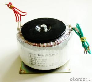
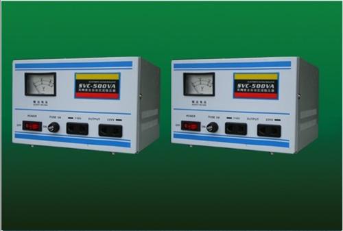
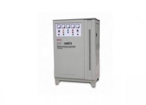
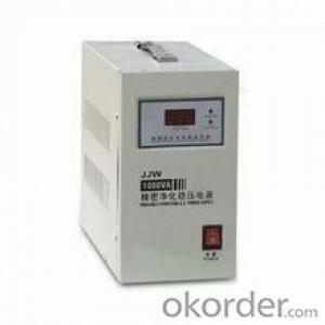
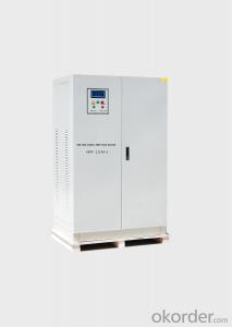
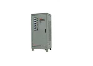
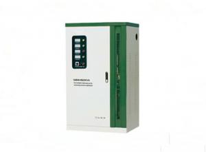
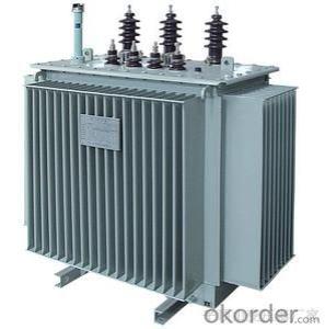
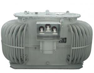
1.Application
DBW SBW compensated voltage stablilizer is a contact adjustable automatic voltage compen-sation high-power regulating power device. When voltage from supply network is varied or dueto loading current effect, it automatically regulates the output voltage to ensure the normal func-tion of the varied of electric equipments.
2.Specification
| Input voltage | Single phase: 220V; Three phases: 380V |
| Output voltage | Single phases: 220V±20% or 220V±30% Three phases four-line: 380V±20% or 380V±30% |
| Phase | Single phase; Three phases four-line |
| Frequency | 50Hz/60Hz |
| Response | within 1 sec.(against 10% input voltage deviation) |
| Efficiency | Better than 95% |
| Ambient temperature | -10oC~+40oC |
| Waveform | Non-lack fidelity waveform |
| Insulation restortion | Better than 5MΩ |
| Overload | Double rated current, one min |
| Protection | Overvoltage, overcurrent, feed phases |
3. Outline and packing
| Type | Outpower(kVA) | Outline(cm) | Weight(Kg) | Qty/CTN |
| DBW-20K | 20 | 70 x 50 x 135 | 283 | 1 |
| DBW-30K | 30 | 70 x 50 x 135 | 310 | 1 |
| DBW-40K | 40 | 70 x 50 x 135 | 330 | 1 |
| DBW-50K | 50 | 80 x 60 x 150 | 360 | 1 |
| DBW-60K | 60 | 80 x 60 x 150 | 380 | 1 |
| DBW-70K | 70 | 80 x 60 x 150 | 100 | 1 |
| DBW-80K | 80 | 90 x 70 x 170 | 430 | 1 |
| DBW-100K | 100 | 90 x 70 x 170 | 480 | 1 |
| SBW-50K | 50 | 80 x 62 x 135 | 350 | 1 |
| SBW-60K | 60 | 80 x 62 x 135 | 370 | 1 |
| SBW-100K | 110 | 85 x 52 x 150 | 420 | 1 |
| SBW-150K | 150 | 100 x 72 x 170 | 550 | 1 |
| SBW-180K | 180 | 100 x 72 x 170 | 570 | 1 |
| SBW-200K | 200 | 100 x 72 x 170 | 630 | 1 |
| SBW-225K | 225 | 110 x 80 x 180 | 660 | 1 |
| SBW-250K | 250 | 110 x 80 x 200 | 700 | 1 |
| SBW-300K | 300 | 110 x 80 x 210 | 740 | 1 |
| SBW-320K | 320 | 110 x 80 x 210 | 760 | 1 |
| SBW-400K | 400 | 110 x 80 x 210/2 | 1100 | 2 |
| SBW-500K | 500 | 110 x 80 x 210/2 | 1500 | 2 |
| SBW-600K | 600 | 110 x 80 x 210/2 | 2200 | 2 |
| SBW-800K | 800 | 85 x 100 x 220/3 | 2800 | 3 |
| SBW-1000K | 1000 | 85 x 100 x 220/3 | 3500 | 3 |
| SBW-1200K | 1200 | 85 x 100 x 220/3 | 4100 | 3 |
| SBW-1600K | 1600 | 110 x 110 x 220/4 | 5560 | 4 |
| SBW-2000K | 2000 | 110 x 110 x 220/4 | 7100 | 4 |
- Q: Is the LTC transformer a regulated voltage transformer?
- If equipped with a load regulator is called on-load tap-changer If equipped with no load regulator is called no-load voltage regulator
- Q: A step up transformer has 5,000 turns in the secondary coil and 200 turns in the primary coil. The primary is supplied with alternating current with an effective voltage of 900V. (A) What is the voltage in the secondary coil? (B) If the current in the secondary coil is 20A, what current flows in the primary coil? (C) What power is developed in the primary coil? (D) What power is developed in the secondary coil?
- a) (5,000/200) x 900V 22,500V. (5,000/200) 25:1. b) (20 x 25) 500A. c) (900 x 500) 450,000W. (22,500 x 20) 450,000W. (450KW). Both must be the same, if no losses.
- Q: I have to build a transformer which are the main formulas or some source that explains this
- You need to specify what the transformer is to be used for. (why do you have to build a transformer ?) (the characteristics of the core are critical to the design) Until you specify that, only the simplest of basics relating to turns ratios can be stated: 1 - Power in primary Power in secondary 2 - Voltage ratio turns ratio 3 - Current ratio 1 / (turns ratio) [from #1 #2] 4 - Impedance ratio Turns ratio squared. [ from #2 #3] **IF** it is a power transformer, I suggest getting a transformer with the same, or slightly higher POWER rating, then simply re-wind the secondary using #2 above. (I did) or Google: how to design transformer windings then pick the one that suits your needs best.
- Q: i just obtained a transformer from a small ac-dc converter. usually, it converts the 240v ac (let's call it terminals a and c) to 4.5v dc (terminals d and c).what if i connect a 4.5 dc supply to the terminals d and c? meaning that where i would usually obtain the converted electricty, instead, i connect a 4.5 to it, leaving the terminals where i would usually connect to the wall empty. wouldn't the magnetic field step up to 240v?
- TRANSFORMER BECOMES SMOKING IN A FEW SECONDS IF THE 4.5V DC HAS HIGH ENOUGH CURRENT.
- Q: Can someone tell me what happened to the primes in transformers. I know Sentinel,Optimus and the fallen but what happened to the others ?
- Depends on the continuity. Traditionally, there were not seven, but thirteen original Primes. Neither Optimus or Sentinel were one of the originals, whether you want to say that there are thirteen or seven. Prime is simply a title given to the leaders of the Autobots, passed down from the original transformers. Since you said seven, I'm assuming you meant movie continuity. In that case, Megatronus Prime, later to be known as The Fallen betrayed the Primes' laws of peace, hence his name. The other six used their physical forms to create a vault in which to hide the Matrix of Leadership from The Fallen. The lore from other continuities is much more interesting however. The fate of those versions of the original Primes range from death, to splitting into smaller transformers and scattering across the galaxy, to living in their own pocket dimension in peace, or to chronicling the history of Cybertron, albeit with their true identity hidden.
- Q: I I am looking to buy a 208 to 480 transformer, would I simply buy a 480 to 208 and reverse the input and outputs? it's a 3 phase system and it is being supplied by an 80kW generator, then straight to an ATS to switch power from normal to emergency.
- Yes, a transformer can be used to either step up or step down the voltage. The rating of a transformer is in KVA, so you can load it to the nameplate rating either way. One thing to consider though is your system ground. When you tie your generator feed back through your step up transformer and then to the ATS . The normal power source feeding your ATS is probably a 3 phase 4 wire grounded WYE system, and your step up transformer will probably have a 3 wire Delta primary. You need to be careful, especially if your ATS feeds any single phase loads. In that case, get a transformer with a WYE - WYE winding configuration. Make sure you follow the NEC code recommendations for a separately derived source.
- Q: Sichuan transformer manufacturer that a best?
- Sichuan Meishan New Transformer Co., Ltd.'s products have the strongest load capacity, up to 200%
- Q: LED non-isolated drive transformer (two windings) calculation method
- General non-isolated auxiliary windings according to chip drop VCC operating range. T = 1 / f Dmin = Vout / Vin (max) Ton = T * Dmin Id = Io * 0.3 (0.3 for the ripple current coefficient) Inductor voltage V = Vinmin-Vout-0.6 (Schottky voltage drop) Lmin = V * dt / di If there are problems please go to the big bit of the forum electronic transformer plate
- Q: I would like to get my grandchild all the transformer movie dvds but don't know the names of all of them. please help and thanks
- Wow that's the best gift you could give ! I would be thrilled to get that ( and I'm a teenager, LOL ). Someone already took my answer. :( But yeah I'll repeat it anyways: Transformers, Transformers: Revenge of the Fallen, and Transformers: Dark of the Moon ( BTW I heard it comes out November 15th, not September 30th, I'd get that checked out ). What a lucky grandchild, I'm buying them all on blue-ray when the third one comes out : If he has a game station (xbox 360 or ps3) why not get him the games? :p too much? okay nvm.hope I helped
- Q: i just got back from seeing transformers and the special effects were awesome but the storyline could have been better. I thought the girl meghan fox was so prettywho thought the same?
- I agree, although a lot of people thought the movie was amazing, the real thing I liked abut it was the special effects, fight scenes, and Bumblebee! Who doesn't want a car that can turn into a robot? But yeah the storyline/acting wasn't that great, although there were a few times where i laughed.
Send your message to us
DBW SBW Compensated Voltage Stabilizer
- Ref Price:
-
- Loading Port:
- Shanghai
- Payment Terms:
- TT OR LC
- Min Order Qty:
- -
- Supply Capability:
- 10000pcs pc/month
OKorder Service Pledge
Quality Product, Order Online Tracking, Timely Delivery
OKorder Financial Service
Credit Rating, Credit Services, Credit Purchasing
Similar products
Hot products


Hot Searches
Related keywords

