


Rectifier Transformers of ZS9 ZSF9 ZSZ9 ZSG9 Series
- Ref Price:
-

- Loading Port:
- China Main Port
- Payment Terms:
- TT or LC
- Min Order Qty:
- -
- Supply Capability:
- -
OKorder Service Pledge
OKorder Financial Service
You Might Also Like


1. Product Description:
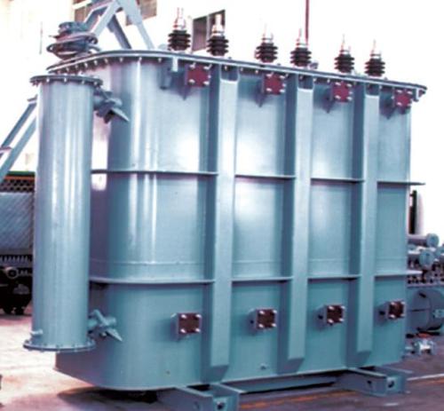
ZS, ZSF,ZSZ, ZSG series rectifier transformers are widely used in controlled siliconrectifier power supply and silicon rectifier power supply. They are mainly usedin aluminum, magnesium and zinc smelting, nitric acid, chemicals, pesticides production,electrolysis, electroplating, and traction etc.
There is electrostatic shielding between primary and secondary coils (networkside to valve side) can be electro statically shielded.
The rectifier transformer with two secondary windings and phasedifference of 30°, 15°, and ±7.5 ° for 6-phase and 12-phase rectification canbe designed and produced for users.
2. Product Characteristic:
l Ambient temperature :-30℃—40℃
l Mean annual temperature is +20℃and below +20℃(if it’s water-cooling product, the highest daily average temperature of cooling-water is +25℃)
l Altitude is not more than 1000m.
l Installation site should be without seriousvibration, bumps and chemical corrosion,
3.Specification:
Provide product specification code and usage (load type).
Tap range, connection symbol, short-circuit impedance.
Special environment should be informed such as altitude, chemicaldeposition, dirt, corrosive media, etc., for dry-type transformers insulation shouldbe provided.
Special products can be designed and manufactured according to customer’special requirement.
for indoor and outdoor use.
Voltage grade: 6-35kV,
Frequency: 50-60Hz
Capacity: 30-20000kVA
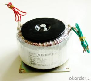
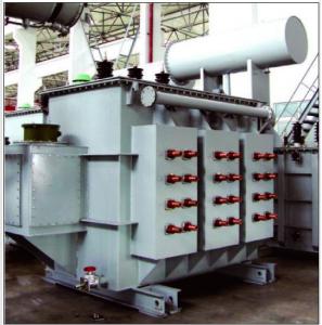
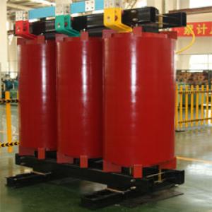
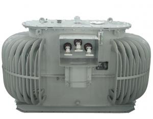
4. Reference Picture:


- Q: How to connect in parallel the following transformers:a) Dy1 Dy11b) Dd0 Dd6
- I don't recognize your transformer designations in a) and b). Perhaps they are industrial transformers that I am not familiar with. My background is electronics, not power distribution. That being said, I'm not sure why you would want to connect transformers in parallel. Possibly to handle a load that exceeds the capacity of one transformer. If this is the reason, it would be better to split the load between two transformers if at all possible. If it is a single load that can't be split, the turns ratios for the two transformers would have to be exactly the same. For that matter, the transformers should be exactly alike, to make sure that they carry the load equally. (A higher source impedance in one transformer would cause the other transformer to carry more than its share of current.) Then it is very simple: connect like terminals together, taking special care to line up the phases. If for some reason you are unable to identify the phase (commonly marked with a dot next to the winding on a schematic diagram), do the following: 1. Connect the primary windings together, wire 1 to wire 1, wire 2 to wire 2. 2. Connect one wire in the secondary of one transformer to a wire in the secondary of the other transformer. 3. Carefully apply power. 4. Measure the voltage between the two loose secondary wires. It should be zero. If not, change one of the wires in step 2 above.
- Q: I wanted to watch the transformers cartoons but because there is so many I don't know which to watch first, seconds etc.Can you please tell me in order which to watch?I'm watching Transformers Season 1 episode 1 atm.THANKS
- If you want to watch the show that started the whole Transformers, Go on google and look for Transformers Generation 1. That will give you the original transformers cartoon to come out. You can google for a list of them or wiki it. But the List i Got Goes like this. #1. Transformers Generation 1 #2. Transformers: The Headmasters #3. Transformers: Super-God Masterforce #4. Transformers: Victory #5. Transformers: Zone After that starts the beast wars series of transformers then the New Age transformers such as armada,energon, and cybertron, and finally the current airing on cartoon network Transformers: The Animated Series. I personally enjoyed generations one the best, as i watched when i was younger but i hope that helps you out in your search or on what ever you wanted to know.
- Q: For example, if you have a battery that puts out 1 amp, can you use a step down transformer to turn that into 1000 Amps. Or is there some sort of limit to how much one can increase current in a circuit?
- you need to understand first that there are actually four most basic units in electricity. these are: v voltage I current, measured in amps r resistance measured in ohms VA w power, measured in watts 1A x 1V 1W 1A @ 1V over 1mm^2/1m pure copper produce 1ohm resistance it is bit more complicated than that. but you must remember that basic power equation is exactly that! it will never grow bigger or smaller, it's left side will always equal it's right side! now deliver from it another two: 1W 1A x 1V 1A 1W / 1V 1V 1W / 1A now, to your question, disregard remark about direct current, we will use inverter or anything else to change our direct current to alternate current. for clarity, i will use only decimal numbers: a battery with 1A/100V capacity, - your question is if you can increase that to 1kA? yes! just use transformations above: 1A x 100V 100W i want 1000A, therefore, re write the equation: 1A 100W / 100V :/x 1000 1000A 100W / 0.1V this is theory in practical solutions, transformers are good, but still incur up to 3% loses, resistance will incur another up to 32% loses due to heat and increased resistance, this is often countered by very effective heat exchange systems and cooling effects as a result. hope this help at least a bit
- Q: Transformer oil filter method
- Transformers in the run after a period of time, if due to short circuit and other causes of transformer oil quality electrical test failed to test the need for oil treatment, improve its purity. The main reason for failure is excessive water content, including other impurities. Transformers because it has been oiled and can not be all out of all the oil out of the filter processing.
- Q: How to use a multimeter to determine the quality of small transformers
- Generally with the smallest ohm file to measure whether the primary tap, if not, then damaged. Use the X10K stall above the ohm stalls to measure the primary and secondary, primary secondary and iron core for short circuit or leakage. If there is connectivity, then the insulation is bad or has been burned or breakdown.
- Q: I have a US Navy Plate and Filament Transformer Manufactured by Hudson American Corporation.This monster weighs 14.5lbs, and is in a sealed steel casing.There are 16 unlabeled terminals, and I'm working to identify those.It does however have the current and voltage labelings for the primary and secondaryPrimary : 110/115/120v AC (Since there are 16 taps, I'm guessing that these are separate primaries)Secondary 1:360-0-360 200MA DCSecondary 2: 6.6v 10A CTSecondary 3: 12.6V 3ASecondary 4: 5.25V 3AI'm set on using a solid state rectifier circuit so i don't need the 5.25V Line, or the 12.6V line.Could I somehow do something to get extra current on the B+ line (S1 windings) with these unused secondaries?I want 4x 6550/kt88, so the extra plate current would be great to have around.
- You can probably draw a bit more from the 720 volt winding if you don't use some of the other windings. Also if you use SS rectifiers, you will get more DC voltage than normal, about 490-500 volts, so the extra drop you would get at higher current may be ok. Or you could use a choke input filter instead of a cap input to get about 350 volts, enough to operate KT88's, and get more current. Watch out for over heating. edit: Electrolytic caps would be a lot smaller than the ones you have. The two chokes in parallel could be used as a choke input filter. Exactly what voltage and current do you need?
- Q: If you have two 12 volt transformers and if we connect their hot wires together does the voltage become 24 or 12 volts? Please help, thanks so much!lt;3
- If you connect them in series, you will get 24 volts. It's not a real good idea to connect them in parallel.
- Q: I am a transformer factory salesman, the company let go to the field to run business, if you go to a strange city, where the main starting from where the few places, and which units to contact? If the local sales in the transformer factory, then work well to carry out? What are the sales channels?
- 1. Power supply company tender 2. Cabinet manufacturers 3, the installation company 4, direct customers, to the planning bureau to find, in advance to know which new project 5, design institute, know some late 6. Power supply company front desk, people come to install more late
- Q: I have a transformer 12v and 12v need to reduce these further to be able to grow or shrink the rotational speed electromotor.Which device or component would be used to reduce the speed of electromotor?I making a mini escalators
- A transformer has AC output, so first get DC, which needs a rectifier and capacitor. Following this is a voltage regulator using an LM317 (adjustable 3 terminal regulator). This can delivers ~1 amp. You should know what maximum current your motor draws under load. The first link is an example for 1.25V-15 V with an 18V transformer. Use a 12V transformer, and a 1000 ohm potentiometer as a variable resistor instead of 2000 ohms (R2). This will give voltages from 1.25V to 7.0V DC. Use the formula to calculate other resistors for a different voltage. Get the LM317 in a TO220 package, and you will need a heat sink, at least as big as in the picture. You can probably find a kit of parts for this in an electronics shop.
- Q: i have a flyback transformer that i want to make a tesla coil out of and i need a diagram for the wiring configuration.
- The modern flyback transformer is also used to generate the DC operating voltage for the TV set. You have a lot more wires than you need to use. You need to get a copy of the wiring from someplace like a Sears repair shop and hope you don't have a built-in high speed diode and filter cap in the same package. The last thing you need is to try to run your Tesla coil from a DC source on the primary. I believe Ramsey electronics makes a package Tesla kit that runs off a flyback. Your coil will not produce a very large brush discharge but it should be a good demonstrater which will have a safe, low current spark.
Send your message to us
Rectifier Transformers of ZS9 ZSF9 ZSZ9 ZSG9 Series
- Ref Price:
-
- Loading Port:
- China Main Port
- Payment Terms:
- TT or LC
- Min Order Qty:
- -
- Supply Capability:
- -
OKorder Service Pledge
OKorder Financial Service
Similar products
Hot products


Hot Searches
Related keywords

