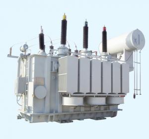
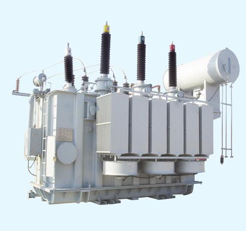
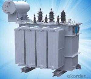
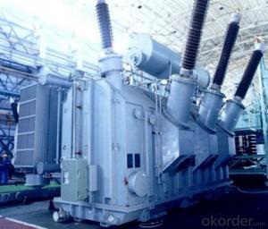
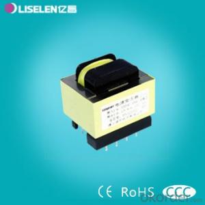
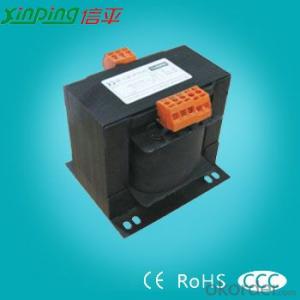
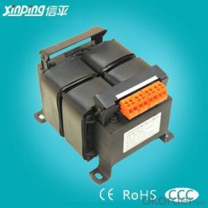
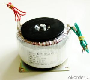
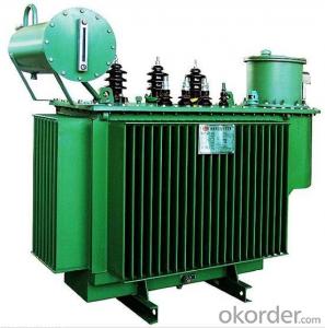
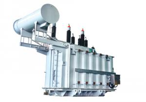
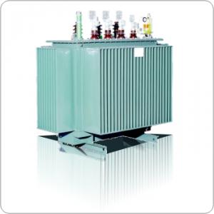
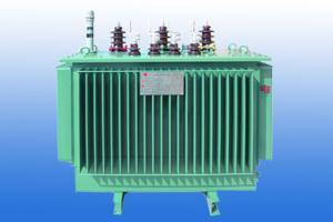
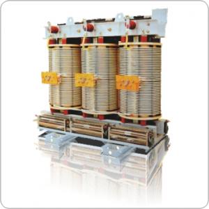
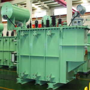
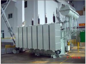
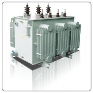
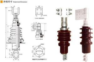
Class 10KV S11 series transformer
- Loading Port:
- Shanghai
- Payment Terms:
- TT OR LC
- Min Order Qty:
- -
- Supply Capability:
- 1000sets set/month
OKorder Service Pledge
OKorder Financial Service
You Might Also Like
Type description 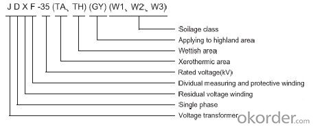
Technical characteristic
1.It accords to the GB1207-1997<voltage transformer> ,IEC186 and IEC60044.
2.This product has the character of limited tightness.All the tightness compartment do not be put into ultraviolet radiation so that we solve the problem of chap of tightness rubber and aging,these product is more reliable and has longer life,we ensure that it can run 20 years without leakage.
3.The porcelain is equipped with irragateing flange.the surface of flange use hot zincification to enhance the wholly mechnism of product and has beautiful outlook.
4.This product is equiped with bellow and is tightnesds completely.
5.With higher accuracy to 0.2,we can reach the requirment of customer with seperatly measuring secondary winding and protection winding.
6.With epoxy secondary terminal board,the product is enhanced secondary insulation and tightness.
7.All the standard comparthent are plated Dakelo.We ensure that the product don't rust for 20 years.
8.The inner structure of this product has changed largly and we solve the problem of old 35KV PT with unreasoned inner structure for the unpassed dielectric loss,This product has low partial discharge and litter dielectric loss with advanced workcraft.
9.The excitaton density of this product is equal or less than 0.7T and has the ability of avoiding ferro-resonance.
Technical Data
| Type | JDXF-35 | |
| Rated voltage | Primary winding | 35/ |
| Measuring winding | 0.1/ | |
| Protection winding | 0.1/ | |
| Residual voltage winding | 0.1 | |
| Frequency | 50HZ | |
| secondary accuracy and reated output | Measuring winding | 80VA 0.2 class |
| Protection winding | 150VA 0.5class 250VA 3P class | |
| Residual voltage winding | 100VA 6P class | |
| Rated limit output | 2000 | |
| Rated insulation level | 4.05/95/200 | |
| Creepage distance | 810,1050,1250 | |
| Flash distance | 410-500 | |
| Total weight/Oil weight | 40/190 | |
| Pack size | 580×600×1300 | |
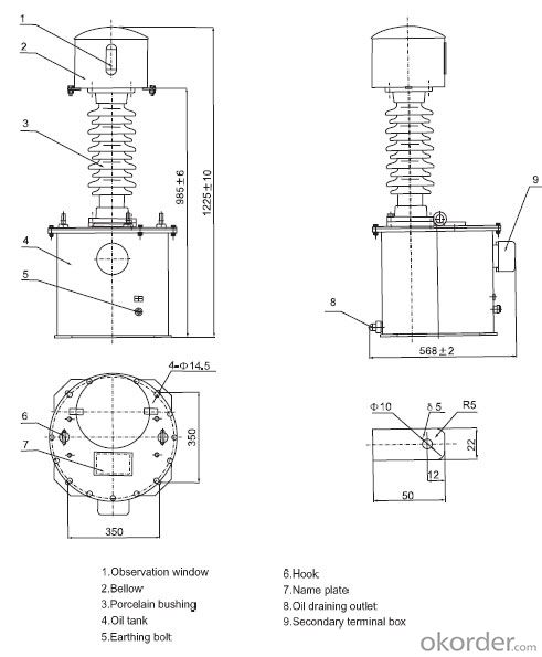
JDXF-35 Voltage Transformer Outline Drawing
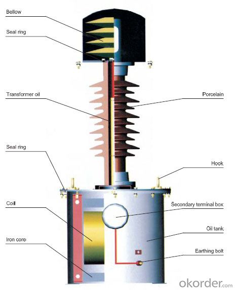
Srructure drawing
- Q: i think transformers
- Simpsons for sure:]
- Q: I want you guys to tell me if the movie transformers its a good movie or not? Why?Thanks, See Ya!
- The Transformers was a marriage of two of the biggest Blockbuster Producers in the business today.Speilberg and Michael Bay (Bad Boys, Armageddon, The Rock)So expect Mind Blowing effects thanks to what Bay Brings to the table and Speilberg brings to the table a relentless perfectionist approach to all of his films.Having said this. If you are a die hard Transformers fan, you'll revel in homages paid to the original animated movie and TV series Optimus Prime's Voice is done by the same man who did the voice for the original character If your not a fan, you'll get a believeable display of vehicles shifting into 15-30 foot robots. The robot effects are stellarthe action sequences are dizzying they happen in rapid succession. The quirks in the characters are really what make the movie shine. From the military personel to Anthony Anderson's portrayal of a high strung, know-it-all hacker the characters really sell the drama. Shai plays his character to the hiltreally no suprise why he's Speilberg's next it boy. The chemistry between Him and Fox is realnot forced and contrived (see Affleck Tyler in Armageddon) There were scenes in which they made the Autobots (the good robots) Less than menacing trying to communicate with todays lingo/slang learned from the world wide webOne of the cleverist twists I think was the way they had Bumblebee communicate through song lyric via the radio Great Soundtrack.great acting (for the most part) If I were to rate Transformers on a scale from 1-10, I would give it 8.5. It does what it was meant to do very well.entertain. Worth the $20 to buy it or the $5 to rent it.watch it a couple time to catch all the little hidden twists and hits in the movie
- Q: If you use a power transformer (120VAC to 12VDC) past its secondary amperage, will it burn up or will it just not supply sufficient power?
- If you are wiring the Transformer in parallel with a battery, this MAY work. Be careful to observe POLARITY (+) and (-) this is critical. First of allthe VOLTAGE of the battery and the Transformer must be the SAME.12VDC or thereabouts. If your load (device you are hooking up) draws more Amperes (AMPS) then the Transformer will supply, the battery WILL make up the difference. The problem will come.if you let the battery get too low and the transformer has to do provide more AMPS than it is capable. You could end up burning up the Transformer OR an internal component of the Transformer. To prevent this, place a FUSE in-line with the output (+) of the Transformer that is rated at the same AMPS that the output of the Transformer AMPS. Please put ANOTHER fuse in-line with the output of the Battery/Transformer combo line that is rated just above the AMPS of your Load device. This will protect both your equipment AND the battery AND your Wiring. This has all the earmarks of a learning adventure if done safely.
- Q: Transformer Amorphous Alloy and Silicon Steel Sheet Advantages and Disadvantages
- (5) from electrical performance. In order to reduce the shearing amount of the core piece, the core of the whole product is composed of four separate core frames, and each phase winding is set on the two separate walls of the magnetic circuit. The magnetic flux in each box in addition to the fundamental flux, there are three harmonic flux exists, a winding in the two volumes of the core frame, the third harmonic flux in the opposite phase, the value of equal , So that the third harmonic flux vector in each set of windings is zero. Such as the primary side of the D connection, there are three harmonic current loop, when the induced secondary side of the voltage waveform, there will be no third harmonic voltage components
- Q: I haven't seen Dark of the Moon, but I recently got OBSESSED with Transformers. Please don't spoil anything, but I'm curious, how do they incorporate the new chick, Rosie, Huntington-Whitely, in the movie? Do they ever explain where Micheala went(Btw- I KNOW what happened to Megan in real life.that's not what im asking lol) So yeah, thanks!Bq: SAY OPTIMUS PRIME IF YOUR A GIRL TRANSFORMER FAN:)Bq: Do MOST girls like Transformers, or is it mostly guys who like it?
- OMG I freaking love transformers! I hate the new girl though!All they say about megan is that they broke up OPTIMUS PRIME
- Q: For example, if you have a battery that puts out 1 amp, can you use a step down transformer to turn that into 1000 Amps. Or is there some sort of limit to how much one can increase current in a circuit?
- Transformers do run on AC, but they step current and voltage up or down along with some heat losses. Theoretically there is no limit to the stepping up of current, but it has to be inline with the magnetic saturation of the primary and secondary coils. In other words you can't put in one turn in the primary with one amp and in the secondary have 1000 turns and expect a 1000 amp outlet current. You have to to base the primary circuit on how much magnetic flux it can produce with how many turns of wire. Like maybe 1000 turns in the primary and 1 million turns in the secondary will get that thousand amps. Plus you have to make sure you have the laminated silicon steel plates that can handle all the eddy currents from the fluctuating alternating magnetic fields and the heat that produces. But anyway, to my knowledge there is no limit to stepping up or stepping down current or voltage as long as you size the wires and core properly to handle the load running thru it
- Q: i am planing to get the eee pad transformer, can it download anything from the internet browser just like a computer does or it can only download apps from its own app store like ipad does. should i get the transformer or ipad 2 ?
- i flow to attempt to make this record as clean as a danger with out growing to be use of too a lot words: reward of the iPad 2: - Intuitively simplistic (too simplistic to a pair peoples style) - Polished - eighty grams lighter (uncertain no remember if honestly anybody notices that :P) - extra helpful app shop (and stable now graphically some extra desirable ideal video games) reward of the Asus transformer: - swifter (not in many circumstances a substantial vast difference) - Flash help - - TIP: *DISABLE* flash each and each time you don't like it on the asus transformer, reason it improves velocity a lot (apple desperate for the guy that he's not allowed to prepare flash, asus/android believes the guy can take care of a few accountability) - not in straight away forward words a intake (examining/gaming) gadget, yet _can_ be used for production besides - extra helpful battery (because of the dock) - extra desirable ideal show - fairly various customization (you would be waiting to as appropriate run laptop OS's on it :D, yet it fairly is in simple terms for nerds) *My suggestion: in case you may carry your breath for some extra desirable months i ought to suggestion you to watch for the Asus Transformer 2, in any distinctive case the iPad 2 and Asus Transformer a million are fairly matched, yet i think of the Asus Transformer ought to nonetheless have the side*
- Q: describe a stabilised transformer
- A stablized Transformer is to step dwon or step up the voltage which is called stabilizer also.
- Q: What is the meaning of the transformer 'turns ratio'? what's the effect?
- The turns ratio of the transformer is the ratio of the transformer, that is, the ratio of the turns of the original coil and the secondary coil. Role: reflects the original transformer, vice coil voltage RMS ratio. In the case where the no-load current is negligible, the magnitude of the original and secondary coil current is inversely proportional to the number of turns. transformer Transformer (Transformer) is the use of electromagnetic induction principle to change the AC voltage of the device, the main components are primary coil, secondary coil and core (core). The main functions are: voltage conversion, current conversion, impedance conversion, isolation, voltage regulator (magnetic saturation transformer) and so on. According to the purpose can be divided into: power transformers and special transformers (electric furnace change, rectifier, frequency test transformer, voltage regulator, mine transformer, audio transformers, IF transformers, high-frequency transformers, impact transformers, instrument transformers, electronic transformers , Reactors, transformers, etc.). Circuit symbols commonly used as the beginning of the number. Example: T01, T201 and so on.
- Q: a lamp is connected to a secondary coil ( 80 turns) of a transformer by long leads which have a resistance of 2.5 ohms. Primary coil( 1600 turns voltage is 220v). the power input to the primary coil is 44w. 1) what is the voltage across the secondary coil2) what is the current across the secondary coil3) what is the electrical power dissipated in the lamp
- Assuming perfect transformer. turns ratio 1600/80 20:1 secondary voltage is 220/20 11 volts primary current is 44/220 0.2 amps secondary current is 0.2 x 20 4 amps drop across wires is 4 x 2.5 10 volts. This assumes the 2.5 ohm number is for both leads, not each. voltage across lamp is 11v – 10v 1 volt power in lamp is 1 v x 4 a 4 watts. .
Send your message to us
Class 10KV S11 series transformer
- Loading Port:
- Shanghai
- Payment Terms:
- TT OR LC
- Min Order Qty:
- -
- Supply Capability:
- 1000sets set/month
OKorder Service Pledge
OKorder Financial Service
Similar products
Hot products
Hot Searches
Related keywords
