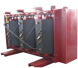
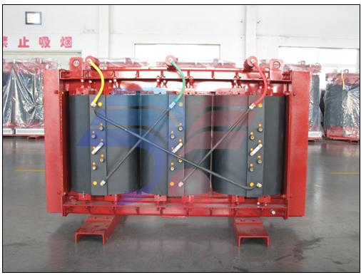
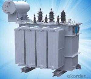
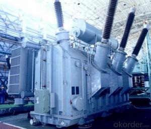
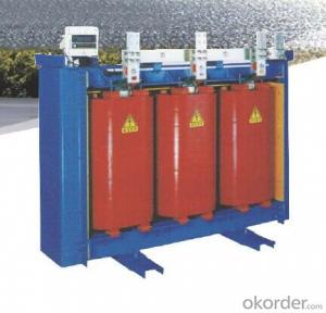
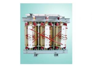
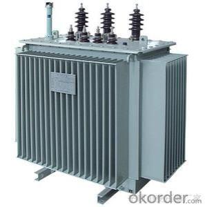
Amorphous Alloy Core Dry-type Transformer of SCBH15
- Loading Port:
- China Main Port
- Payment Terms:
- TT OR LC
- Min Order Qty:
- -
- Supply Capability:
- -
OKorder Service Pledge
OKorder Financial Service
You Might Also Like
SCBH15 Series
Amorphous Alloy Core Dry-type Transformer
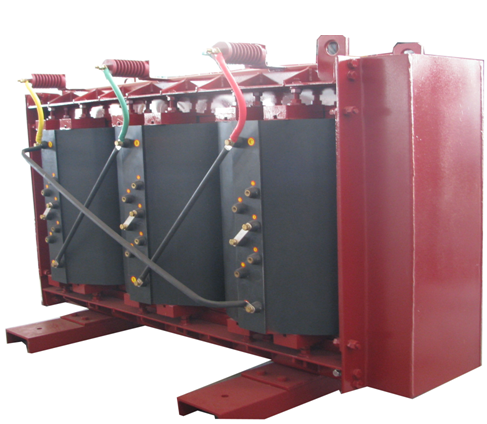
SCBH15 series amorphous alloy core dry type transformer is an efficient and energy savingnew type distribution transformer. It is acombination of technologies of amorphous alloy transformer and cast resin dry typetransformer and has the advantages of oil free, flame retardant,self extinguish, resistant to moisture, anti-cracking, free maintenance, and especiallylow no load loss. It has been widely used in railway, airport,station, high building, business center, and industrial and miningenterprises. It is particular well suited to inflammable andexplosive places.
Characteristics
●Low loss
Especially no load loss, 75% lower than ordinarytransformer at the same capacity, drastically reducingits operating cost and has obvious effect on energy-saving.
●Strong anti-short circuit capacity
Three-phase five-limb structure and frameprotection structure around iron core effectively ensure the capability of anti-short circuit.
● Low noise
The combination of reasonable design and carefultechnique makes the noise of products lower than the requirement of nationalstandard JB/10088.
● Highhumidity proof
HV&LV coils arevacuum epoxy cast resin, can be operated in 100% relative humidityand other harsh environment.
● Low temperature rise
Coils adopt thin resin structurewithout cracking and have strong ability for heatdissipation and overload.
● Flame resistance, self-extinguishment, explosion proof and no pollutionto environment
Glass fiber and other insulating materials used in coilsare self-extinguish and can not cause fire hazard because of electric arcproduced by short circuit.
Using Condition
●Altitude:less than1000m.
●Max.temperature: less than 40℃.
●Min.temperature: -5℃.
●Max.monthly average temperature: 30℃.
●Max.yearly average temperature: 20℃.
●Noobvious pollution in installation environment.
●Indoor
Insulating Level
Voltage Grade (kv) | The highest voltage effective value of equipment (kv) | Rated short-time applied withstand voltage (kV/min) | Rated lightning impact withstand voltage (peak) (kv) |
≤1 | 1.1 | 3 | -- |
6 | 7.2 | 20 | 60 |
10 | 12 | 35 | 75 |
Performance Parameter
Capacitance (Kva) | Voltage Assembly (kv) | HV tapping range (%) | LV (KV) | Connectiion | No-load loss (W) | No-load current (%) | Load loss (75℃)W | Impedance Voltage (%) |
200 | 6 6.3 6.6 10 10.5 11
| ±5 Or ±2×2.5
| 0.4 | Dyn11
| 200 | 0.7 | 2200 | 4 |
250 | 230 | 0.7 | 2400 | |||||
315 | 280 | 0.7 | 3020 | |||||
400 | 300 | 0.6 | 3480 | |||||
500 | 360 | 0.6 | 4260 | |||||
630 | 430 | 0.5 | 5150 | |||||
630 | 420 | 0.5 | 5200 | 6 | ||||
800 | 480 | 0.5 | 6070 | |||||
1000 | 550 | 0.4 | 7100 | |||||
1250 | 660 | 0.4 | 8460 | |||||
1600 | 750 | 0.4 | 10240 |
Outside Dimension
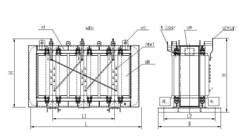
Type | Uk% | Dimension (mm) | Kg Weight (Kg) | ||||
L | B | H | L1 | L2 | |||
SCBH15-200/10 | 4 | 1450 | 1000 | 1230 | 660 | 660 | 1450 |
SCBH15-250/10 | 1650 | 1000 | 1280 | 660 | 660 | 1700 | |
SCBH15-31510 | 1700 | 1000 | 1290 | 660 | 660 | 1950 | |
SCBH15-400/10 | 1710 | 1050 | 1290 | 660 | 660 | 2230 | |
SCBH15-500/10 | 1750 | 1050 | 1300 | 820 | 660 | 2580 | |
SCBH15-630/10 | 1800 | 1100 | 1320 | 820 | 660 | 3210 | |
SCBH15-630/10 | 6 | 1850 | 1100 | 1310 | 820 | 660 | 3150 |
SCBH15-800/10 | 1930 | 1150 | 1330 | 820 | 660 | 3500 | |
SCBH15-1000/10 | 2080 | 1200 | 1360 | 1070 | 820 | 4390 | |
SCBH15-1250/10 | 2160 | 1200 | 1380 | 1070 | 820 | 4910 | |
SCBH15-1600/10 | 2300 | 1250 | 1450 | 1070 | 820 | 6050 | |
Note: Outsidedimension is only for your reference.
Ordering basic data
1、Rated capacity;
2、Rated voltage;
3、Rated frequency;
4、Tapping range;
5、Impedance voltage;
6、Using condition;
7、Other performance data should be indicated in thecontract.
- Q: How to understand the secondary side of the transformer
- The transformer consists of iron core (or core) and coil, the coil has two or more than the winding, which connected to the power supply winding called the primary coil (a test), the rest of the winding called secondary (secondary side). The basic principle of the transformer is the principle of electromagnetic induction, now single-phase double-winding transformer as an example to illustrate its basic working principle: When the primary winding with voltage U1, the current I1 flow, in the core to produce alternating magnetic flux , These magnetic flux known as the main flux, in its role, both sides of the winding were induced potential E1, E2. Transformer two sets of coil turns are N1 and N2, N1 for the primary, N2 for the secondary. In the primary coil plus an AC voltage, the secondary coil will produce both ends of the induced electromotive force. When N2> N1, its induction The electromotive force is higher than the primary voltage. This transformer is called a step-up transformer: when N2 <N1, its induced electromotive force is lower than the primary voltage, which is called a descending transformer. Primary secondary voltage and coil The number has the following relationship: U1 / U2 = N1 / N2 Suppose that n is the voltage ratio (turns ratio). When n <1, then N1> N2, U1> U2, the transformer is a step-down transformer, otherwise it is a step-up transformer.
- Q: Find the transformer ratio of a transformer having 350 turns on the secondary winding and 7000 turns on the primary. What RMS voltage must be applied to the primary of the transformer to develop an open-circuit secondary voltage of 63 V? if a load of 100 ohms is connected to the secondary winding what is the primary current, ignoring resistive and reactive losses in the transformer?
- you're on the outstanding song with the remark approximately ratios. yet another substantial ratio is the impedance ratio of a transformer, that's the sq. of the turns ratio. So, in case you have a prevalent with 12.6K and a secondary with 8.05, then you definately've an impedance ratio of (12600 / 8.05) 1565.2 and hence the turns ratio would desire to be the sq. root of this, or 39.fifty six. i think of that, given the above, you could decide section B now, outstanding?
- Q: i bought transformers a few months ago, and i finally watched it last night.my nephew watched it and i guess got something on the dvd.i was at the ending where they rolled bumblee in on the truck and the cube was destroyed and all that and optimus prime was saying they lost a great ----- i can't remember extactly what he said.anyway, right after that, the cd skipped and went do directly to the credits.what did i miss?
- I think he says they lost a great warrior. The Autobots stay on Earth and will try to live peacefully among humans. Sam and Michaela end up together. They also leave it open for a sequel because one of the bad robots (the tiny one that tried to break into the government's system before the Australian girl caught him) escapes back to his home planet. Presumably to bring back more of the bad Transformers. I have read that they plan to begin shooting the sequel soon - will possibly be out in the summer of 2010.
- Q: What are the specifications of the transformer capacity?
- Select the transformer capacity, to the existing load as the basis, appropriate consideration of load development, select the transformer capacity can be determined in accordance with the 5-year power development plan. When 5 years of power development is clear, little change and then the load is not less than 30% of the transformer capacity: ?? ?SN = KS ΣPH / (cosφ η) ?? ?Where: SN - box change in 5 years required configuration capacity, kVA ΣPH - 5 years old with financial calculations, kW KS - at the same time, generally 0.7 to 0.8 Cosφ - power factor, generally 0.8 ~ 0.85 Η - transformer efficiency, generally 0.8 ~ 0.9 ?? ?According to the formula generally KS = 0.75, cosφ = 0.8, η = 0.8 ?? ?SN = 0.75ΣPH / (0.8 × 0.8) = 1.17ΣPH ?? ?Example: a district in accordance with 50W / m2 design, then ?? ?PH = 50 × 19200 = 960kW ?? ?SN = 1.17 x 960 = 1123 kW ?? ?So the district selected three 400kVA transformer.
- Q: Can anyone explain what each wire does in this spicific microwave transformer
- The bottom coil with the 2 tabs is the primary. The 2 red wires leading off to the right is a low voltage secondary with high voltage insulation so that they remain isolated from the other windings. It powers the filament of the microwave tube. The other red wire leading off to the left is one end of the high voltage secondary. It normally connects to a high voltage rectifier and capacitor and then to the cathode of the tube via one of the filament connections. You can expect to see negative pulses in the 2000-3000 volt range at that connection with an available current that is several times the lethal level. The other end of the high voltage secondary is grounded to the frame of the transformer at the rivet at the top center. The anode (plate) of the tube is also grounded through its mounting hardware. Most microwave transformers run hot even when lightly loaded since they are run fairly close to saturation on the B-H magnetization curve. You'll need a fan if you are using it for extended periods. If you carefully remove both secondaries and the steel magnetic shunts wedged in between the primary and secondary windings, you'll have the foundation for winding your own transformer good for about 400-600 watts. First add about 10 more turns to the primary which will cut the core losses significantly by running it lower on the curve. Expect to see about 1 volt per turn on any new secondaries you wind. Don
- Q: i rememeber when i was a lil kid i used to watch Beast Wars on friday nights. I think it was back in 2000 or so. It was pretty cool too; as opposed to transforming cars, etc, there were transforming animals. also there werent any humans.imo the new transformers animation sucks, though the movie was greatim sure Beast Wars and Transformers are related because they used names like Megatron and Octomus Prime (sp?)so yeah. what happened to Beast Wars?
- Transformers G1 was the cartoon from the eighties. This story line had the transformers crashing to earth during the time of dinosaurs and remaining inactive until some volcanic activity reactivated the ship they were in which then repaired them. Beast Wars is actually in the future of G1. These transformers travel back in time inadvertently to the same time period when the G1 characters came to earth, but the G1 characters were inactive. I am not familiar with the transformers cartoons after Beast Wars. There were 3 seasons of Beast Wars and 4 seasons of Gen 1, all available on DVD.
- Q: I am building a high voltage air cored RF transformer.The transformer primary will be powered by a 12V square wave signal around 5-20kHz. The secondary needs to put out at least 1kV at very low amperage (less than 1A, the lower the better).The output will be used to charge a high voltage capacitor in a resonant circuit.What considerations I need to take into account in building the transformer?Thanks for all the help!
- Last transformer I made had a 1000 volt secondary, a 28 volt primary, ran at 22kHz, and a 20mA capability. It was wound on a ferrite form and was a cube about 1.5 inches on each side. I had a lot of difficulty keeping it from shorting out. I used lots of special HV insulating tape between winding layers, and managed to get a few working, but it was difficult. It was used in a voltage doubler to generate 2500 volts DC, so the entire winding had to withstand that voltage. Remember that there are only a few volts between consecutive turns, but after a hundred turns, that builds up to hundreds of volts. .
- Q: Where is the transformer used?
- You ask more general, there are many kinds of transformers, 1 is the power transformer, it is 10,000 volts drop to 380,220 V commonly used low pressure for us to use. Small transformers are 220V voltage reduced to household appliances used when the operating voltage rectified as electrical power. High-frequency transformers are generally used as switching power supply pulse output transformer. High-frequency signal transformer only a few turns of the coil, the transmission of high-frequency signal. Simply say this kind of bar, a wide range of various types of transformers.
- Q: Exactly what is the storyline of the Transformers. As far back as I know, there were two brother, Unicron and Primus who fought each other because Unicron wanted to suck up Universes. But where did these two come from? Does it even say?
- I am a fan but I haven't been able to find that out myself, if you find out let me know.
- Q: After the calculation, due to the different cooling, the current density is different, I finished a winding section 96.5mm ?, secondary winding section 1562.5mm ? What are the specifications of the copper row? Another request for a transformer copper specifications table.
- A general use of cable out, select 120mm2 line can be; second to use two 100 × 10mm copper, copper is to tin treatment. Copper specifications table recommended to find the national standard, see the copper discharge capacity and installation methods, after all, the transformer must be produced to meet the national standard.
Send your message to us
Amorphous Alloy Core Dry-type Transformer of SCBH15
- Loading Port:
- China Main Port
- Payment Terms:
- TT OR LC
- Min Order Qty:
- -
- Supply Capability:
- -
OKorder Service Pledge
OKorder Financial Service
Similar products
Hot products
Hot Searches
