


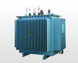
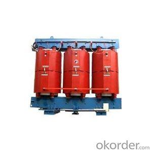
Cast resin dry type transformer 10-35kV
- Ref Price:
-

- Loading Port:
- China Main Port
- Payment Terms:
- TT OR LC
- Min Order Qty:
- -
- Supply Capability:
- -
OKorder Service Pledge
OKorder Financial Service
You Might Also Like


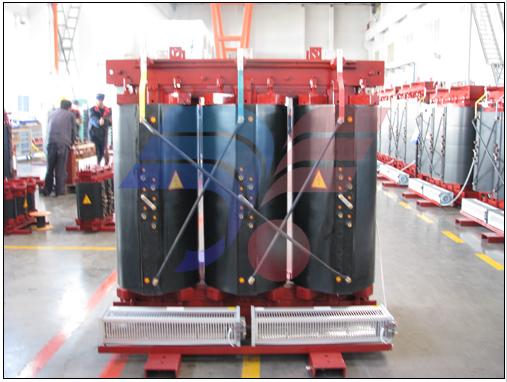
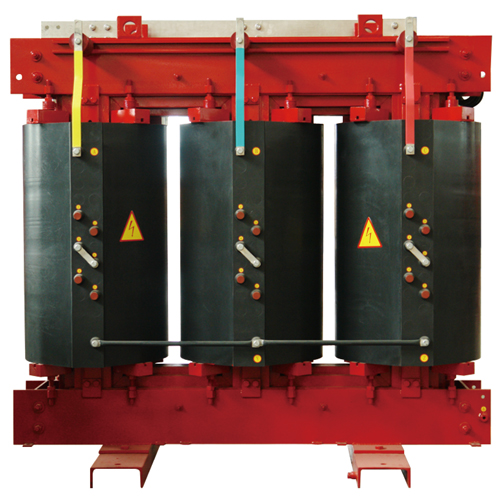
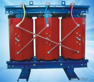
Cast resin dry-type transformers
1. Features
SC(B) Series Cast Resin Dry type Transformers (CRDT) are produced by using full auto vacuumcast transformer software technology of thin insulating tape filling from Germany HTT MASCHINEN GMBH, full-auto vacuum cast equipment from GermanyHeydrich GMBH, High-Low voltage foil winding machine from France BR company,full-auto silicon steel sheet cut-to-length line from Germany GEORG GMBH, highquality epoxy cast resin materials and high-permeability grain-oriented cold rolled silicon steel sheets. Based on advanced technology, raw materials with high quality, scientific management and complete inspection manners, the features of the product are as follows:
Coils are covered by glass fiber and moulded by epoxy cast resin material under vacuum,which has the advantages of perfect mechanical performance, no cracking, nobubbles inside, little partial discharge, high reliability and long servicelife.
Better humidity resistance. CRDT can be operated in severe environment and high humidity by reasons that HV&LV coils adopt high-temperature moulding structure with low hygroscopic and clamps for core are anti-corrosion.
Flame retardance, explosion proof and friendly environment. Insulation materials (such as glass fiber) used for coil are not very flammable and can be self-extinguishing,electric arc resulted from short-circuit cannot start a fire. There are nohazardous fire gases from resin under high temperature.
Thin insulation structure and air flues inside can strengthen heat emission and short-circuitoverload capacity.
Low loss and low noise. Core lamination adopts 45° full sloping seam and four orseven level step-by-step system, which improves efficiently the magnetic fluxdistribution at the corner of iron core and reduces no-load loss and noiselevel.
Excellent ability to withstand short circuit and lightning impulse.
Smallsize, light weight, simple installation and free maintenance.
2. Standard
National standard GB1094.11 "Power transformer Part 11: Dry type transformer"
National standard GB10228 "Technical parameters &requirements for dry-type power transformer"
IEC 60076-11 "Power transformer Part 11: Dry type transformer"
DIN 42532 "Cast resin dry-type power transformer"
Machinery industry standard JB/T3837 "Productmodel compilation method for transformer"
Machinery industry standard JB/T10088 " 6kV- 500kV Power transformer sound level"
3. Technical specification
Voltage class: 10~35kV
Capacity range: 30~3150kVA
Voltage regulating mode: no excitation voltage regulation
Tappingrange: ±2×2.5%or ±5%
Frequency:50Hz or 60Hz
Connection symbol: Yyn0 or Dyn11
Short-circuit impedance: standard impedance (See technical parameters)
Peak temperature rise: 100K
Cooling model: AN or AF
Protection level: indoor: IP00, IP20, IP23
Insulation class: class F
Insulation level: 10kV power frequency withstand voltage 35/3kV impact withstand voltage75kV,
35kV power frequency withstand voltage 70 kV impact withstand voltage 145 kV
4. Model coding

5. Operating condition
Ambient temperature: maximum temperature 40 ℃, minimum temperature -5 ℃ (applicable toindoor type transformer), or else based on GB1094.11-2007 and the relevantprovisions
Environmental condition: no harmful smog and steam, no excess corrosive dust, vapor, salt fog,no serious damp and dripping water.
Altitude: less than 1000m, otherwise adjust appropriately in accordance with therelevant provisions.
Insulation class: class F, temperature limit of 155 ℃.
Power waveform and frequency: three-phase power supply voltage approximates symmetry, powerwave approximates sine wave, frequency 50 Hz or 60 Hz.
6. Technical parameter and overall dimension

Dimension drawing without enclosure

Dimension drawing with enclosure
SC (B)9 series 10kV power transformers
Model | Rated Capacity(kVA) | Rated Voltage (kV) | Loss (W) | Short-circuit impedance (%) | No-load current (%) | Connection symbol | Weight(kg) | Overall dimension (mm) L×W×H | Track gauge (mm) | ||
HV | LV | No-load | Load 120℃ | ||||||||
SC9-20/10 | 20 | 6 6.3 6.6 10 10.5 11 | 0.4 | 190 | 650 | 4 | 3.4 | Dyn11 Yyn0 | 230 | 570×600×730 | 300/300 |
SC9-30/10 | 30 | 220 | 750 | 2.4 | 270 | 600×600×740 | 300/300 | ||||
SC9-50/10 | 50 | 310 | 1060 | 2.4 | 360 | 660×600×770 | 300/400 | ||||
SC9-6310 | 63 | 350 | 1230 | 2.4 | 410 | 680×600×770 | 300/400 | ||||
SC9-80/10 | 80 | 420 | 1460 | 2.0 | 490 | 680×600×870 | 300/400 | ||||
SC9-100/10 | 100 | 450 | 1670 | 1.8 | 580 | 700×700×910 | 300/400 | ||||
SC9-125/10 | 125 | 530 | 1960 | 1.6 | 630 | 940×850×1180 | 520/520 | ||||
SC9-160/10 | 160 | 610 | 2250 | 1.6 | 770 | 1110×950×1300 | 520/520 | ||||
SC9-200/10 | 200 | 700 | 2680 | 1.4 | 880 | 1110×950×1350 | 520/520 | ||||
SCB9-250/10 | 250 | 810 | 2920 | 1.4 | 1100 | 1180×1150×1460 | 520/520 | ||||
SCB9-315/10 | 315 | 990 | 3670 | 1.2 | 1190 | 1230×1150×1480 | 660/880 | ||||
SCB9-400/10 | 400 | 1100 | 4220 | 1.2 | 1470 | 1250×1150×1520 | 660/880 | ||||
SCB9-500/10 | 500 | 1310 | 5170 | 1.2 | 1700 | 1250×1150×1550 | 660/880 | ||||
SCB9-630/10 | 630 | 1510 | 6220 | 1 | 2040 | 1360×1150×1600 | 660/880 | ||||
SCB9-630/10 | 630 | 1460 | 6310 | 6 | 1 | 2010 | 1420×1150×1620 | 660/880 | |||
SCB9-800/10 | 800 | 1710 | 7360 | 1 | 2420 | 1480×1250×1670 | 820/1000 | ||||
SCB9-1000/10 | 1000 | 1990 | 8610 | 1 | 2780 | 1570×1250×1760 | 820/1000 | ||||
SCB9-1250/10 | 1250 | 2350 | 10260 | 1 | 3200 | 1740×1250×1800 | 820/1000 | ||||
SCB9-1600/10 | 1600 | 2760 | 12400 | 1 | 3800 | 1850×1350×1840 | 820/1070 | ||||
SCB9-2000/10 | 2000 | 3400 | 15300 | 0.8 | 4400 | 1900×1450×1930 | 1070/1200 | ||||
SCB9-2500/10 | 2500 | 4000 | 18180 | 0.8 | 5650 | 2130×1450×2050 | 1070/1200 | ||||
SC(B) 10 series 10kV power transformers
Model | Rated capacity (kVA) | Rated voltage (kV) | Loss (W) | Short-circuit impedance (%) | No-load current (%) | Connection symbol | Weight(kg) | Overall dimension (mm) L×W×H | Track gauge (mm) | ||
HV | LV | No-load | Load 120℃ | ||||||||
SC10-20/10 | 20 | 6 6.3 6.6 10 10.5 11 | 0.4 | 170 | 620 | 4 | 3.4 | Dyn11 Yyn0 | 230 | 570×600×730 | 300/300 |
SC10-30/10 | 30 | 190 | 710 | 2.4 | 270 | 600×600×740 | 300/300 | ||||
SC10-50/10 | 50 | 270 | 1000 | 2.4 | 360 | 660×600×770 | 300/400 | ||||
SC10-63/10 | 63 | 320 | 1170 | 2.0 | 410 | 680×600×770 | 300/400 | ||||
SC10-80/10 | 80 | 370 | 1380 | 1.8 | 490 | 680×600×870 | 300/400 | ||||
SC10-100/10 | 100 | 400 | 1570 | 1.8 | 580 | 700×700×910 | 300/400 | ||||
SC10-125/10 | 125 | 470 | 1850 | 1.6 | 660 | 950×850×1200 | 520/520 | ||||
SC10-160/10 | 160 | 540 | 2130 | 1.6 | 810 | 1110×950×1320 | 520/520 | ||||
SC10-200/10 | 200 | 620 | 2530 | 1.4 | 930 | 1110×950×1370 | 520/520 | ||||
SCB10-250/10 | 250 | 720 | 2760 | 1.4 | 1250 | 1180×1150×1480 | 520/520 | ||||
SCB10-315/10 | 315 | 880 | 3470 | 1.2 | 1280 | 1260×1150×1500 | 660/880 | ||||
SCB10-400/10 | 400 | 980 | 3990 | 1.2 | 1500 | 1280×1150×1550 | 660/880 | ||||
SCB10-500/10 | 500 | 1160 | 4880 | 1.2 | 1750 | 1280×1150×1610 | 660/880 | ||||
SCB10-630/10 | 630 | 1340 | 5880 | 1 | 2080 | 1400×1150×1635 | 660/880 | ||||
SCB10-630/10 | 630 | 1300 | 5960 | 6 | 1 | 2060 | 1450×1150×1650 | 660/880 | |||
SCB10-800/10 | 800 | 1520 | 6960 | 1 | 2500 | 1500×1250×1710 | 820/1000 | ||||
SCB10-1000/10 | 1000 | 1770 | 8130 | 1 | 2950 | 1600×1250×1800 | 820/1000 | ||||
SCB10-1250/10 | 1250 | 2090 | 9690 | 1 | 3450 | 1770×1250×1840 | 820/1000 | ||||
SCB10-1600/10 | 1600 | 2450 | 11730 | 1 | 4000 | 1890×1350×1890 | 820/1070 | ||||
SCB10-2000/10 | 2000 | 3050 | 14450 | 0.8 | 4650 | 1940×1450×1970 | 1070/1200 | ||||
SCB10-2500/10 | 2500 | 3600 | 17170 | 0.8 | 5900 | 2170×1450×2100 | 1070/1200 | ||||
SC(B) 11 series 10kV power transformers
Model | Rated capacity (kVA) | Rated voltage (kV) | Loss (W) | Short-circuit impendence (%) | No-load current (%) | Connection Symbol | (kg) Weight without enclosure
| (kg) Weight with enclosure | (mm) Dimension (no enclosure) L×W×H | (mm) Dimension ( with enclosure) L×W×H | Track gauge (mm) | ||
HV | LV |
No-load | Load 120℃ | ||||||||||
SC11-20/10 | 20 | 6 6.3 6.6 10 10.5 11 | 0.4 | 150 | 620 | 4 | 3.4 | Dyn11 Yyn0 | 230 | 145 | 570×600×730 | 1100×1100×1200 | 300/300 |
SC11-30/10 | 30 | 175 | 710 | 2.4 | 270 | 145 | 600×600×740 | 1100×1100×1200 | 300/300 | ||||
SC11-50/10 | 50 | 250 | 1000 | 2.4 | 360 | 145 | 660×600×770 | 1100×1100×1200 | 300/400 | ||||
SC11-63/10 | 63 | 280 | 1170 | 2.0 | 410 | 145 | 680×600×770 | 1100×1100×1200 | 300/400 | ||||
SC11-80/10 | 80 | 335 | 1380 | 1.8 | 490 | 145 | 680×600×870 | 1100×1100×1200 | 300/400 | ||||
SC11-100/10 | 100 | 360 | 1570 | 1.8 | 580 | 145 | 700×700×910 | 1100×1100×1200 | 300/400 | ||||
SC11-125/10 | 125 | 425 | 1850 | 1.6 | 680 | 200 | 980×850×1230 | 1400×1200×1600 | 520/520 | ||||
SC11-160/10 | 160 | 490 | 2130 | 1.6 | 830 | 200 | 1150×950×1380 | 1400×1200×1600 | 520/520 | ||||
SC11-200/10 | 200 | 560 | 2530 | 1.4 | 960 | 215 | 1150×950×1420 | 1600×1200×1700 | 520/520 | ||||
SCB11-250/10 | 250 | 650 | 2760 | 1.4 | 1280 | 240 | 1230×1150×1510 | 1600×1400×1700 | 520/520 | ||||
SCB11-315/10 | 315 | 790 | 3470 | 1.2 | 1320 | 240 | 1300×1150×1540 | 1600×1400×1700 | 660/880 | ||||
SCB11-400/10 | 400 | 880 | 3990 | 1.2 | 1550 | 260 | 1320×1150×1590 | 1700×1400×1800 | 660/880 | ||||
SCB11-500/10 | 500 | 1050 | 4880 | 1.2 | 1800 | 270 | 1320×1150×1650 | 1700×1400×1900 | 660/880 | ||||
SCB11-630/10 | 630 | 1210 | 5880 | 1 | 2130 | 280 | 1450×1150×1680 | 1800×1400×1900 | 660/880 | ||||
SCB11-630/10 | 630 | 1170 | 5960 | 6 | 1 | 2120 | 280 | 1480×1150×1690 | 1800×1400×1900 | 660/880 | |||
SCB11-800/10 | 800 | 1370 | 6960 | 1 | 2560 | 310 | 1550×1250×1760 | 2000×1500×2000 | 820/1000 | ||||
SCB11-1000/10 | 1000 | 1590 | 8130 | 1 | 3000 | 325 | 1650×1250×1850 | 2100×1500×2100 | 820/1000 | ||||
SCB11-1250/10 | 1250 | 1880 | 9690 | 1 | 3510 | 335 | 1820×1250×1900 | 2200×1500×2100 | 820/1000 | ||||
SCB11-1600/10 | 1600 | 2210 | 11730 | 1 | 4100 | 380 | 1940×1350×1940 | 2300×1600×2300 | 820/1070 | ||||
SCB11-2000/10 | 2000 | 2720 | 14450 | 0.8 | 4750 | 400 | 1990×1450×2000 | 2400×1700×2300 | 1070/1200 | ||||
SCB11-2500/10 | 2500 | 3200 | 17170 | 0.8 | 6000 | 430 | 2220×1450×2150 | 2500×1700×2500 | 1070/1200 | ||||
Note:All pictures and datum of the products in it are only for your reference, we reserve the right of changing and updating the content, picturesand datum in this paper without prior notice.
7. Temperature control system
The safe operation and service life largely depends on security and reliability of winding’s insulation. When winding temperature is beyond insulation tolerable temperature, the insulation is damaged, which is the main reason that may lead to the transformernot be normally used. BWD3K series temperature control system measures thetemperature of LV winding by PTC temperature measurer and can control coolingfan according to the measured temperature values.
Features:
Integrating of temperature display and control.
The advanced circuit design can effectively restrain circuit drift, andhas strong anti-interference ability
Has Watch Dog function and power failure detection circuit on powersupply to make sure that the thermostat can work well in harsh environment.
According to user requirements to provide the three-phasetemperature value 4-20mA analog output function and RS232 or RS485 computer interface, to meet the requirements of automatic monitoring.
Simple and practical draw type installation, easy to remove.
Main functions:
1.Three-phase winding temperature data-loggingand maximum value display.
2.Automatic open and close fanfunction/manual start-stop function according to set temperature
3.Over-temperature alarm, over temperaturetrip function.
4. Fault detection alarm, mute function.
5. Fan start-stop function on a regularbasis.
* 6. Output and temperature synchronous 4 ~20A standard value electric current.
* 7. RS232 or RS485 computer interface output,communication distance reaches 1200 meters.
Note: "*" is optional.
Product with enclosure: Thecontroller is installed at the LV side.

Product without enclosure: Thecontroller is installed on the clamp supporting plate at the LV side.

8. Overload capacity curve


- Q: i want to know what you think transformers 3 will be about i think unicron will want to eat cybrotron and decticons and autobots work to get her to protect cybertron
- not really didnt megatron destroy cybertron so they might protect earth plus the autobots dont have a way to get there
- Q: A single phase transformer operates from a 230V supply. The primary and secondary resistances are 0.03 Ω and 1.12Ω respectively while the corresponding leakage reactances are 0.1Ω and 6.4Ω; the magnetising branch can be neglected. The secondary winding has four times as many turns as the primary. Calculate :i) The equivalent impedance referred to the primary circuitii) The secondary terminal voltage when the load has a resistance of 200Ω and an inductive reactance of 100Ω.iii) The secondary terminal voltage when the load has a resistance of 200Ω and a capacitive reactance of 100Ω.Can someone show me how to tackle this question please?
- The is something wrong with your leakage reactances or the turn ratio, because N^2Lls/Llp. I'll neglect this issue. i) The total impedance of the transformer referred to the primary is Zt .03+j.1+(1.12+j6.)/16. ii) VloadVin*ZLoad/16/(Zt+ZLoad/16) ii) Same as above, except ZLoad now becomes the parallel combination of 200 and -j100.
- Q: the use of autotransformers is strictly prohibited.
- The double-winding type safety isolating transformer has two windings which are input (primary) windings and output (secondary) windings, and the two windings are insulated from each other, only by magnetic connection, that is, secondary Winding and the earth does not constitute a loop, if the use of additional insulation appliances, you should use a safe isolation transformer. And since the lotus transformer all of its winding are connected, by sliding the position of the contact to change the size of the voltage. Therefore, the autotransformer primary winding (power circuit) and the secondary winding (power supply circuit) is not only between the magnetic connection, as well as the direct connection of the circuit. It and the earth constitute a loop, so it can not be used as a safe voltage power supply. Therefore, the safety regulations: lighting transformers must use double-winding type safety isolation transformer, prohibit the use of autotransformers.
- Q: Hi,Should i wait for the Asus Transformer Pad Infinity, or should i buy the New iPad ?Thanks,Patrick
- Hardware is negligible without software. The Google.play site (Formerly the Android Market) has plenty of apps to choose from. Basically, your investment is in the simplistic ease of the New iPad or the flexibility of Android 4.x. It's really a matter of which O/S you wish to support. I calculate the iPad IPS display has 25.7% more pixels than the new Asus model. Will you even notice the difference? Not at those screen sizes. Besides, the Asus has a 16:10 Ratio for a better movie experience. Personally, I have already seen that even the new iPad can't match wits with a Tegra 3 tablet when running certain games. Comes close, though. I'm waiting with baited breath for the Asus Transformer Pad Infinity. In my opinion, so should you.
- Q: I have been reading wikipedia and have gotten confused.Va.Number of Coils on side a---- ._________________Vb.Number of Coils on side bwikipedia mentioned how power companys use transformers for converting to high voltage power li nes then use transformers to bring the voltage back down.Focusing on the transformer that jacks the voltage upwirea-[side a-Transformerxyz- side b]-wirebso assum wireb is the high voltage power line.--Which side of transformerxyz would have more coils ? My guess is that side b has more coils then side a--Is it safe to say that the wattage of side a is equal to side b?--they said something about magnetic flux, does this just mean that the material connecting side a to side b has to be magnetic?--they said that the insulation wears down in transformers over time due to heat. what is causing this heat?--they said something about leakage and spacing of coils, what does this mean?tyVVVVVVVm
- The previous answer is correct, but the following may be helpful. A transformer works by the linking of changing magnetic flux produced by one loop or coil (the primary winding) with another coil (the secondary). That is why transformers only work with alternating current or pulses. Magnetic iron has the ability to increase the magnetic flux produced by a coil. This is called its magnetic permeability and can increase the flux produced by factors of several thousand or more. Leakage flux in a real transformer is the amount of flux produced by the primary that does not link the secondary. This flux is wasted and reduces the efficiency of the transformer. Heating of the wire insulaltion not only comes from the resistive heat of the windings, but also the heat produced in the magnetic material (core) of the transformer. These losses are called eddy current and hysteresis losses and can be quite substantial. The reason that cores of transformers are laminated (stacked thin sheets of magnetic iron) is to reduce the eddy current losses.
- Q: Are there any transformers action figures that arent for little kids like from the movie and are collectables? LINKS?
- Personally I wouldn't go with the ones from the movie. They're more a kids toys and the quality isn't too good. I go with G1 reissues. The Binaltech and Alternators line. Fun to play with and has collectible value. And the Masterpiece Edition Transformers. Which i do recommend highly. Expensive but worth it. The details look very real. And are collectors items The classics line is good too. They look a lot more decent and a bit better in quality than the current toys.
- Q: Transformer voltage range of 10.5 ± 2 * 2.5% kV and 10.5 ± 5% kV What is the difference
- 1, the voltage range is the same, are 10kV ± 5%; 2, the difference is that the accuracy of different voltage regulator, 10.5 ± 2 * 2.5% kV transformer sub-switch has five stalls, respectively, 10.5 +5% kV, 10.5 + 2.5% kV, 10.5kV, 10.5-2.5% , 10.5-5% kV; and 10.5 ± 5% kV transformer section switch has three stalls, respectively .5 +5% kV, 10.5kV, 10.5-5% kV; 3,10kV transformer sub-switch three more for the power failure regulator transformer, and sub-section switch five for overload regulator of the transformer, relatively speaking, the fifth gear than the third gear section switch Much more complex, so the price should be slightly higher for the load change is relatively large, the voltage quality requirements of the relatively high important occasions.
- Q: I check the voltage between x1 and x2 I got 120v but between x1 and ground on primary I got 40v and between x2 and ground on Primary I have 50v, if I connect x2 to ground won't it short the transformer? Thank you
- I am thinking that your incoming power is 208 volts and you want to convert to 120 volts. If i haven't made myself look foolish, you merely need to use your x1 and x2 wires to continue on as your 120 volt power source. Cap off, do not connect/use the other connections involved on your multi tap transformer. If I have the idea wrong.never mind what i said. To ground the transformer, truly grounded? you need to connect the metal, unpowered shell to a ground. If you mean make a neutral/ground, you don't.
- Q: What is the role of the pebbles in the transformer base
- Transformers base need a pool around the pool inside the pebbles, the role of the pool called the reservoir, that is, when there are accidents, transformer oil leakage, the pool can store oil to prevent the oil flow everywhere, the pool filled with pebbles, in order to Safe, on the one hand is to prevent oil burning. As well as for the convenience of the transformer body above, the following is better than a deep pit convenient? Transformer oil pit volume is calculated in accordance with the transformer oil, there is a certain depth.
- Q: If calculating the efficiency of a transformer with different frequencies,how can the frequency be altered? For the experiment the voltage applied will have to be constant, is this still possible? or what quantities will be kept constant? and which will be measured to calculate the efficiency? using PVI to then use %(Pout/Pin)*100 would mean measuring current and voltage, is this the best way?
- properly no rely what engineering considerable you elect, you may desire to take Calculus a million 2, Matrices, Differential Equations, Chemistry a million 2 with labs, Physics a million 2 (Electromagnetism). you do not easily declare your engineeing considerable till the top of Sophmore 300 and sixty 5 days in college. Junior 300 and sixty 5 days is once you would be formally enrolled in a considerable. once you word for college and choose a considerable, you at the instant are not easily enrolled in that considerable and you will nevertheless choose any considerable you prefer. they merely ask what considerable you have an interest in to verify you're taking the mandatory situations on your first 2 years earlier stepping into your considerable in Junior 300 and sixty 5 days. interior the 1st 2 years of taking chemistry, math, and physics, you may additionally take Intro to engineering(CAD), and a brilliant form of engineering classes and electives like Statics, Dynamics, power of fabric, Thermodynamics, Into to electric powered Engineering(Circuits), C++, or Fluids. those classes will help you make certain what direction to circulate in direction of. based on your description, you desire Mechanical or business Engineering. the two deal in convalescing performance of goods, machines, and approaches. the two have numerous math. the two prefer expertise of Physics and the two require you to be good in difficulty fixing.
Send your message to us
Cast resin dry type transformer 10-35kV
- Ref Price:
-
- Loading Port:
- China Main Port
- Payment Terms:
- TT OR LC
- Min Order Qty:
- -
- Supply Capability:
- -
OKorder Service Pledge
OKorder Financial Service
Similar products


Hot products


Hot Searches
Related keywords

