

SGB 10H grade insulating dry-type power transformer
- Ref Price:
-

- Loading Port:
- China Main Port
- Payment Terms:
- TT OR LC
- Min Order Qty:
- -
- Supply Capability:
- -
OKorder Service Pledge
OKorder Financial Service
You Might Also Like


S (G)B 10H grade insulating dry-type power transformer
1. Model
S------------------------------three phase
G -----------------------------non-encapsulation dry type
B----------------------------- LV foil coil
10 ----------------------------- performance code
□----------------------------- rated capacity (KVA)
□----------------------------- rated voltage(HVKV)
2. General
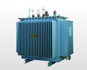
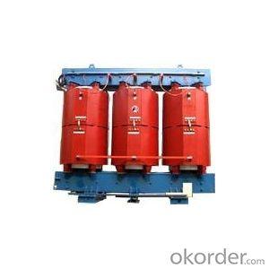
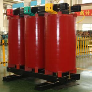
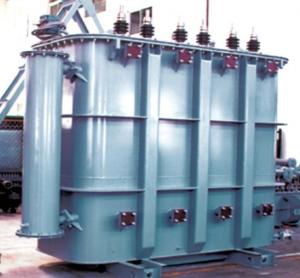
SG10 type-this series dry-type distributing transformer has strong withstanding of thermal shock, overload capability. Beside, it has many good points such as flame-retardant, low-loss, and low partial discharge capacity, low noise, no harmful gas and no pollution. It is insensitive of humidity and dust, compacted, no crack and so it is easy to be maintained. Therefore, it is suitable for the using in the adverse circumstances of high requirement for fire protection, high degree of load fluctuation and dirty, moist, such as airport , power plant, metallurgy, hospital, skyscraper, shopping center, and residential areas and other special environments like oil, chemical industry, nuclear plant, nuke, etc.
1. Technical parameters
Rated capacity (KVA) | Voltage group(KV) | Connection method | Dissipation (KW) | No-load Current (%) | Impedance voltage (%) | Insulating level | Weight (kg) | ||
High- voltage | Low- voltage | No-load | Load (145℃) | ||||||
100 | 11 10.5 10 6.6 6.3 6 | 0.4 | Dyn11 or Yyn0 | 0.40 | 1.88 | 2.4 | 4 | H/H | 520 |
125 | 0.48 | 2.13 | 2.0 | 650 | |||||
160 | 0.56 | 2.55 | 1.8 | 740 | |||||
200 | 0.62 | 3.10 | 1.8 | 850 | |||||
250 | 0.72 | 3.60 | 1.8 | 1005 | |||||
315 | 0.88 | 4.60 | 1.8 | 1270 | |||||
400 | 0.94 | 5.40 | 1.8 | 1465 | |||||
500 | 1.16 | 6.60 | 1.8 | 1730 | |||||
630 | 1.35 | 7.90 | 1.6 | 6 | 1840 | ||||
800 | 1.52 | 9.50 | 1.6 | 2170 | |||||
1000 | 1.76 | 11.40 | 1.3 | 2390 | |||||
1250 | 2.08 | 12.50 | 1.3 | 2990 | |||||
1600 | 2.44 | 13.90 | 1.3 | 3830 | |||||
2000 | 3.32 | 17.50 | 1.2 | 4380 | |||||
2500 | 4.00 | 20.30 | 1.2 | 4930 | |||||
- Q: actually we are trying to make a dc transformer,in which we want variable dc voltage at primary sidewe are doing this by using a rheostatwhich will change the value of current continously thus accordingly the value of voltage varyare we thinking right or wrong????
- Transformers can work on DC Every gasoline engine generates a high voltage AC spark by using DC. This is done by quickly pulsing the coil of an Auto Transformer with DC. THese bursts of power cause a magnetic field to be quickly created and then just a quickly to collapse as the DC burst ends. In older cars this was done by a set of points in the distributor and were operated by a rotating cam. THe points acted like a simple switch turning the power ON OFF very quickly as the cam rotated to direct a spark to each cylinder in turn. It is a rapidly changing magnetic field that induces power into the secondary of the transformer. Your thinking is on track in that a transformer uses the variations in primary current flow to induce voltages on the secondary. Your technique is in error as varying DC with a rheostat is way too slow to be noticed on the secondary. You need a means to quickly chop up the current and create a magnetic field that then expands and collapses in order to induce power in the secondary. Due to the change in direction of the magnetic field as it expands then collapses the voltage produced in the secondary is AC. A very simple way to do this is to use a push button that you can tap on and rapidly pulse the power to the primary. You can then replace the push button with a Buzzer (or relay wired as a buzzer) to chop up the DC. In essence you are then making your own inverter which converts DC into AC. If you have questions send an E-mail and I'll explain .
- Q: How we can check the output wattage of any voltage transformer? For example if we buy a voltage stabliser for television or A/C, how we can be certain that the output watts provided by the stabiliser will suit our appliance? Is there any device to check the output watts, if yes, then how to?Please help.
- The transformer should have a label on it giving it's output capacity in watts or voltamps. The device you want to connect to the transformer should also have a label giving the power draw of the device in watts or voltamps. As long as the transformer has a higher rating than the device you want to connect to it, things should work fine. I would want the transformer to have a little more power capacity than the load I want to connect. If I wanted to connect a 500 watt load, I would prefer at least a 550 watt transformer. A watt is the power used by a device. A voltamp is really the apparent power, but is very close to the actual power. For most purposes, they may be used interchangeably.
- Q: For a project, I need a sine wave with an RMS amplitude of 1000 V at least.I have a function generator that only makes sine waves at most of 7 V RMS.I have a neon transformer w/ a 120 V primary and a 3,300 V secondary and a step down transformer w/ a 120 V primary and 16 V secondary, which is used backwards.Well, I can only get 585 V max. I decided to get some low power step down transformers (Hammond Mfg. 162 series) w/ dual primary and secondary windings. so I can try different combination of step up.I thought the smaller the core would be less of a load for the generator. I get 30 V out of the HVAC tran. (10 VA rating) when the big transformer is hooked up, but for a Hammond w/ a similar winding ratio and (1.1 VA) w/ a similar winding ratio, but I can only get like very little out of the big transformer when hooked up.Is there another factor. I read something about transformer impedance, I was thinking of doing a quick measurement of that on them.
- You are confusing VA (power ratings) with transformer ratios 120/16 7.5 :1 3300/120 27.5 : 1 So connect 7Vrms to 16 input to give output 1 52.5V Now connect this 120 (52.5V) output to the 120V input of the 120/3300 transformer The output should be approx 52.5 x 27.5 1444 Volts Use the 16/120 to step up and then the 120/3300 to step up again Take the function generator voltage to its lowest and measure at all points now gradually increase the generator voltage measuring at all points until you get what you want If the voltages are not as you expect then the VA ratings may be a problem Remember to be extra careful with High Voltages
- Q: What is the vacuum impregnation of the transformer?
- so that the transformer immersed in vacuum under the conditions of the paint, so you can rule out the bubble inside the winding, increase Insulation performance. Dip out after drying.
- Q: I use transformers in my circuitry all the time but when a transformer is say a secondary 12v 1a transformer than what does it mean by 1 ampis it that the secondary winding wire will pop after 1 amp doo to the simple thinness of the wire? or that the ohms of the secondary coil, when using iv/r, 112/12so does this tell you that the coil is 12 ohms?please don't give me other information about the transformer just answer the question please.
- It means the transformer secondary voltage is 12 volts and the current rating is 1 amp. If you put a higher current load on the transformer it won't pop, but it will overheat and the insulation will degrade faster than if the current was kept below 1 amp. If the current is allowed to go too high, the transformer will fail in a short time.
- Q: The specification states that the 35KV substation is capable of obtaining the power supply after the main transformer is powered down. Therefore, in this case, the transformer used should be connected to the power supply side of the circuit breaker. My question is that the main transformer which, the main transformer is not connected to the power supply side of the circuit breaker?
- Main Transformer: Main transformer, referred to as the main transformer, English name: generator step-up transformer, referred to as GSU transformer or GSU. The main transformer refers to a unit or substation of the total step-down transformer, its capacity is generally relatively large. Other transformers used as power distribution, commonly known as distribution transformers, the capacity is slightly smaller. On the main transformer protection, as the main transformer, in general, relatively large capacity, requiring a higher reliability of the work. For different capacity of the transformer, the required installation of the protection category is not the same. Transformers used: In general, substation high voltage switchgear need to provide 220V power supply, DC screen also need 220 power supply continued float. As in the operation of high voltage cabinet, there is no low-voltage power supply, so in the high-voltage cabinet set a very small capacity of the transformer. Thus providing the first power supply required for the operation of the high voltage cabinet. When the transformer is put into operation, the low voltage cabinet has the second power supply of the low voltage power supply circuit, and then automatically switches to the normal low side power supply as the operating power source. Features: Thermal stability, high reliability, long service life. Low loss, low noise, maintenance-free. Small size, light weight, less space, low installation costs.
- Q: how to ground transformers at substations??
- an earth ground is made at the transformers sub-station. This is made by driving a copper rod (uffer?)deep into the earth,the depth set by the size of said transformer.A portion of the (uffer?)or ground rod is left exposed and a ground wire/strap is attached to it
- Q: Can someone all the Transformers stuff? I mean, I see a lot of stuff about 'G1' and 'G2' and I think I heard something about their being TONS and TONS of different storylines for it.Will someone name each storyline, and what G1 and G2 is, and please tell me the official canon usage?
- I'd like someone to explain these dumb Action movies to me too!!! :
- Q: I have a 34kv/380/500KVA transformer and it loads a pump of 450HP/2200V. Starting current reaches up to 1700 amps for around 3-4 seconds using a soft starter. The rated capacity of the transformer is 700amps and the pump running current is 689 amps.Any calculations to prove that the transformer is enough to provide the application would be a help.thanks.
- Damn, had to read the question before I realized it has NOTHING to do with Optimus Prime or Megatron. (*laughing*)
- Q: From the following transformer, how would I calculate:a) the equivalent impedance on the low-voltage sideb) Converting the impedance found in (a) to it's per-unit quantities
- a) the turns ratio of the transformer is 20 to1 so to refer an HV side impedance to the LV side you divide it by the square of the turns ratio which in this case is 400 which gives: 0.001+j0.00025 ohms. b) There's a certain amount of freedom in doing this for you may define the per-unit impedance base however you want. It is however rather usual to define it as VA / I^2. Here I 5000/2400 2.083 amps So base impedance HV side 5000/2.83? 624 ohms making the given impedance (0.4+j0.1)/624 p.u. This p.u. value should be the same on either side of the transformer. Nice to see you around again but do I notice you haven't improved at saying please when you want someone to do something for you for nothing. If you can't learn that there's not much use in learning all these technical skills. You're going to remain a clumsy oaf!
Send your message to us
SGB 10H grade insulating dry-type power transformer
- Ref Price:
-
- Loading Port:
- China Main Port
- Payment Terms:
- TT OR LC
- Min Order Qty:
- -
- Supply Capability:
- -
OKorder Service Pledge
OKorder Financial Service
Similar products


Hot products


Hot Searches
Related keywords

