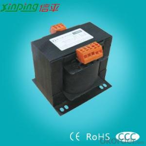
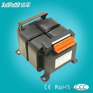
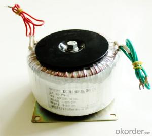
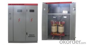
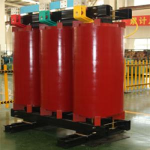
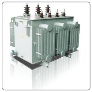
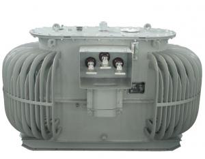
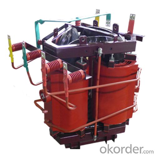
DKS Series Grounding Transformer
- Loading Port:
- China Main Port
- Payment Terms:
- TT or LC
- Min Order Qty:
- -
- Supply Capability:
- -
OKorder Service Pledge
OKorder Financial Service
You Might Also Like
1. Product Description:
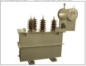
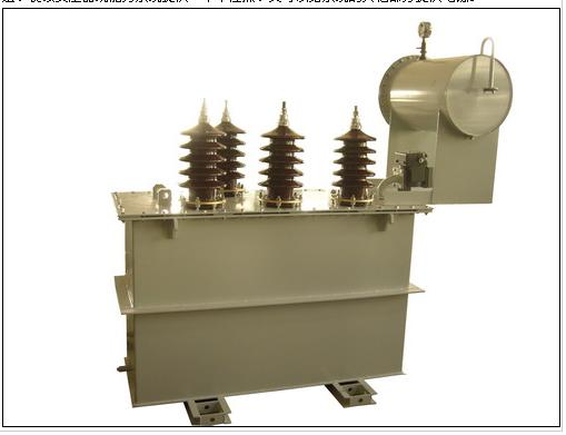
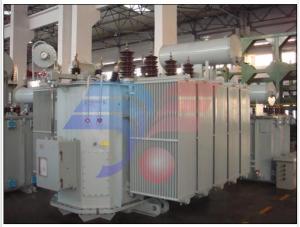
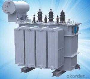
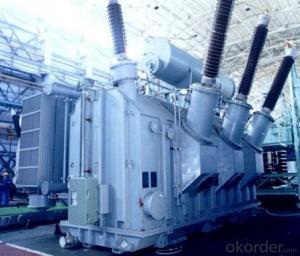
The grounding transformer is usedin the three phase power system with neutral insulation, to provide artificial neutral point.
This neutral point can be directly grounded. It can also begrounded by reactor or arc suppression coil. With a secondary winding,
the grounding transformer can not only provide a neutral point for system but also provide power supply to other parts of system.
2. Product Characteristic:
Special environment should be informed such as altitude, chemicaldeposition, dirt, corrosive media, etc., for dry-type transformers insulation shouldbe provided.
l Mean annual temperature is +20℃and below +20℃(if it’s water-cooling product, the highest daily average temperature of cooling-water is +25℃)
l Altitude is not more than 1000m.
l Installation site should be without seriousvibration, bumps and chemical corrosion,
3.Specification:
Type | Primary rated capacity (kVA) | Secondary rated capacity (kVA) | Rated voltage (kV) | Neutral point voltage (A) | Outline Dimension L x W x H |
DKS-200/6 | 200 | 6.3 | 50 | 1260×850×1460 | |
DKS-315/6 | 315 | 10.5 | 50 | 1580×900×1500 | |
DKS-400/6 | 400 | 8.3 | 100 | 1610×910×1550 | |
DKS-630/10 | 630 | 10.5 | 100 | 1640×950×1600 | |
DKS-315/10 | 315 | 50 | 10.5/0.4 | 50 | 1740×975×1670 |
DKS-315/10 | 315 | 160 | 10.5/0.4 | 50 | 1755×990×1600 |
DKS-630/10 | 630 | 250 | 10.5/0.4 | 100 | 1800×1010×1800 |
4. Reference Picture:
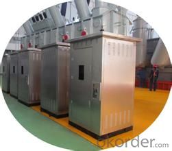
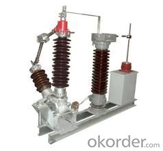
- Q: i heard a new was coming out ,i hope so ,the first two rocked!!!
- Transformers 3 is estimated for a July 1, 2011 release.
- Q: I love the Transformers movies and games to death, but I've never ever been able to like the cartoons.I know they were somewhat popular, especially as the first Transformers game was a huge successplease add why you like/dislike it.thanks in advance
- I hated the old transformers cartoon movie with a passion. Mainly cause my ex used to watch it over and over and over again, and Cry at the optimus part every freakin time. By the time we broke up, I wanted all transformers things to die. I'm recovering slowly.
- Q: Hello everyoneI have a 110V hardware plugged in at home (we use 220V) by way of a step down transformer and I was wondering if transformers 'use' more power than usual. I don't want a nasty electircal bill.Because even when the hardware is 'off', the transformer itself is still on. It still hums. I am wondering if the transformer is constantly pulling power out of the wall socket 24/7 if I leave it on.Any help will be greatly appreciated. Thanks all.
- A transformer like one you are using is called a step-down transformer because it is changing the source voltage 220vac to 110vac. The answer is yes; it will draw current even though you have no load on the secondary side. This is because the coil on the source side (primary) has a constant current flowing through it; it is a closed loop circuit. The secondary winding(s) produce current flow through electromagnetic inductance by their close proximity to the primary coil. Your rate of current will not be as high if you have a closed circuit on the secondary but current will continue to flow unless you open the circuit on the primary side. I bet that not only does it hum (magnetic field) but it is also warm to the touch. Heat equals energy loss and the energy must be coming for someplace.
- Q: Transformer oil filter method
- So only on-line oil treatment. Oil filters require an external oil filter and oil tank. The new oil (has been qualified, insulation pressure are qualified oil into a clean oil tank inside, the external oil filter and oil drums and transformer tubing as a whole, the external circulation of online filter oil). Mainly: 1, online filter to continuous operation, to ensure that the weather is fine air humidity less case, under the conditions of the best conditions for 214 hours of continuous operation.
- Q: I saw the first one, thought it was great, and the second one was even better. But are they planning on making another one? If so, do you know what its going to be about?IMO, i think it should be about Unicron, yes that would be kool haha.
- yes, Transformers 3 is the working title for the third film in the live action Transformers series, directed by Michael Bay and produced by Steven Spielberg. It is the sequel to Transformers: Revenge of the Fallen and is scheduled for release on July 1, 2011.
- Q: I love the movie transformers and cant wait till part 2.Anyone know anything about it specifically???
- If you look at the movie as just a movie it's great but if you look at it and expect it to resemble the original cartoon than it doesn't hold up as well. I know nothing about the pending sequel but I'm hoping they find a way to include the dinobots that doesn't seem too outlandish.
- Q: Before engaging any technician i want to gather some knowledge about planer transformer. It will be good if u have any suggestions.
- While operating under the same laws of physics and using the same materials (i.e. copper, ferrites) like the conventional transformers, these Planetics? planar transformers have different construction geometry that reflects handful of technological advantages.
- Q: 50KVA transformer each phase current maximum band
- Transformer output power is apparent power, and active power (KW) relationship: apparent power = active power × power factor. With an average power factor of 0.8, the 50 KVA transformer can be the load power (50 KVA × 0.8) 40KW of active power. Transformer (Transformer) is the use of electromagnetic induction principle to change the AC voltage of the device, the main components are primary coil, secondary coil and core (core). The main functions are: voltage conversion, current conversion, impedance conversion, isolation, voltage regulator (magnetic saturation transformer) and so on. According to the purpose can be divided into: power transformers and special transformers (electric furnace change, rectifier, frequency test transformer, voltage regulator, mine transformer, audio transformers, IF transformers, high-frequency transformers, impact transformers, instrument transformers, electronic transformers , Reactors, transformers, etc.). Circuit symbols commonly used as the beginning of the number. Example: T01, T201 and so on.
- Q: I would like to know if its possible to create my own transformer- preferably by producing my own windings. My goal is to make an open-air transformer encased in an acrylic box. I would like it be able to withstand a 15A load at 120V. I want the windings to be 1:1 so that the power is just transferred through the magnetic field, not stepped up or stepped down.The purpose would be to power my PC through it, just because I think it would be cool to look at the box and imagine the energy transferring through the air to my screen. Obviously, it's doing that out in the street, and a thousand other places before it gets to me, but I don't get to see any of it!Any one have any suggestions? If it's way to difficult or expensive to make my own inductors, what kind of inducts would I need to buy, and how close would the need to be to each other?
- a 15a load is way more than you need for a PC, which probably needs 1 or 2 amps at the most. If you really want to make a 15*120 1800 watt transformer go ahead, but it's a lot more work than a 1*120 120 watt one. You will need a transformer core, which you can buy, or salvage out of an old transformer of the proper power level, and a lot of wire. You need to calculate the proper wire size and number of turns, and get enough enameled wire to do that. Transformers are not made of inductors or inducts, but of turns wound on a laminated iron core. Make sure the box has ventilation holes in it, as this may get hot. You do realize that a mistake may result in lots of smoke and perhaps a fire? And you could get burned, or electrocuted? And your terminology leads me to believe your knowledge in this area is close to zero. Be sure to use fuses as part of your design. Use the buddy system, have someone within hearing distance at all times with a fire extinguisher, and that person should have knowledge of what to do to cut the power. .
- Q: I was very disappointed with Transformers 2, there was no acting way too much action. Does anyone else feel the same way?
- For what it was, i think it was a good movie. It wasnt meant to be competing with strong movies with a powerful story. Just action entertainment. You need to put it in perspective with what it was meant to be.
Send your message to us
DKS Series Grounding Transformer
- Loading Port:
- China Main Port
- Payment Terms:
- TT or LC
- Min Order Qty:
- -
- Supply Capability:
- -
OKorder Service Pledge
OKorder Financial Service
Similar products
Hot products
Hot Searches
Related keywords
