

63MVA/220KV startup/standby transformer for factory
- Ref Price:
-

- Loading Port:
- Tianjin
- Payment Terms:
- TT OR LC
- Min Order Qty:
- 1 pc
- Supply Capability:
- 1 pc/month
OKorder Service Pledge
OKorder Financial Service
You Might Also Like


Quick Details
| Place of Origin: | HeBei | Brand Name: | CNBM | Model Number: |
|
| Usage: | Power | Phase: | Coil Structure: | Toroidal | |
| Coil Number: | 3 Winding | Capacity: | Rated Voltage: | 63MVA/220KV | |
| Connection Symbol: | YNd11 Dyn11 YNyn0d11 | Tank: | Cover type or Bell type | OLTC: | MR or ABB or SMS |
Packaging & Delivery
| Packaging Detail: | Mainbody --naked Disassembled parts -- crate |
| Delivery Detail: | 3 months |
Specifications
1. CESI certificate
2. High short-circuit withstand
3. Low loss, PD and noise
4. CTQC certificate
5. No leakage
Description
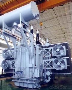
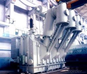
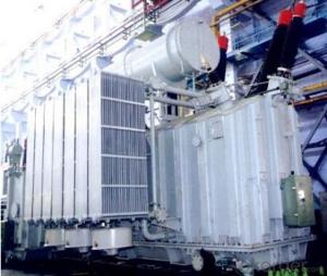
The application of the 63MVA/220KV startup/standby transformer, and matches well with the transmission capacity of UHV lines, which has wide prospect of application. Because of its large capacity and large volume, the whole transportation weight with nitrogen is about 200-490 tons, and due to the restricted transport conditions, the transportation becomes the critical issue for application of the 63MVA/220KV startup/standby transformer. In order to make the products applicable to any UHV substation in our country, the state grid of corporation of China set the "A study of easy-transport large capacity UHV Transformer” as a key scientific research projects, and entrusted BTW to carry out the research.
During the process of research and development, BTW adopted the advanced design technology and modular design, the transformer can be transported disassembly and with advantages of compact core and winding body, less transportation weight and low transportation cost, effectively solves the need of UHV construction in the transportation restricted areas. By using the most advanced 3D magnetic field calculation software, BTW performed detailed analysis and calculation for the magnetic flux leakage and eddy current loss of the transformer coil, iron core and oil tank steel structures. Besides, by using of the advanced electric field calculation software, BTW performed detailed analysis and calculation of main longitudinal insulation, and mastered the arrangement of the main longitudinal insulation of large capacity UHV transformer and the control of distribution of winding magnetic flux leakage. All of which make the products with low loss, low noise, small volume, strong anti short circuit ability, no local overheating and other significant advantages, and guarantee the long-term safe and stable operation.
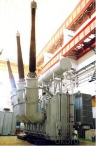
The world's first on-site assembled large capacity UHV Transformer’s right at the first time once again filled the gap in the field of UHV transformer research after Chinese transformer industry overcame the difficulty of integral transport of the 63MVA/220KV startup/standby transformer, which marks BTW has fully occupied the world transformer industry technical peak. The successful development of the product filled the gaps in the domestic technology and met the urgent need of UHV construction application in our country, greatly improved the technical level and manufacturing ability of BTW in terms of UHV Transformer products.
- Q: A small transformer used in a foundry has 550 primary turns and 20 secondary turns. Initially, the switch on the secondary side of the transformer is open, so there is no connection between the two ends of secondary coil.(a) What is the voltage difference between the two ends of the secondary coil, Vs, if a direct current potential of Vp 120 V is placed across the primary coil? (That is, the frequency of oscillation on the primary is zero.) (b) What is the voltage difference between the two ends of the secondary coil, Vs if Vp is 120 V and the frequency of oscillation on the primary is 60Hz? (c) Now equipment powered by the transformer is put into use and the switch is closed. A resistance of 14 Ω is placed between the two ends of the secondary coils. What is the current through the secondary coil? (d) What is the current through the primary side of the coil with the switch closed? Thanks so much!!
- A. Zero, since dc current does not have a varying magnetis field. B. 550/120 20/ X 4.3636volts Ne /E p Ns / E s C.4.3636v / 14 .311 a. Es / R t A s D. .011 amp if the transformer is 100% efficient
- Q: If I have a primary coil and secondary coil each with 400 turns that acts as a transformer, and the primary potential difference is 2.988 V, and the secondary potential difference is 0.0551 V.I need to find the efficiency. Ideally, it would be 100%, but this is the real world. So I did N(turns) and Volts and used the equation [N(p)V(s)/N(s)V(p) ] *100%p primarys secondaryNturns of coilV potential differenceI had an answer of 1.84% which seems awfully low. Help please. Thanks!
- You are right. The efficiency is that low. Take a look at it another way: Pin Pout if 100% efficient. Since we know a 1:1 turns ratio will produce the same voltage from one side of the transformer to the other, the current produced on the secondary is extremely low to pull the voltage down to .0551V. It makes this transformer extremely inefficient! I can't even think of how you would design a transformer that was this inefficient. I think even a large OD iron nail with a lot of eddy currents at 7.5k Hz I believe would be more efficient. The next worst way I can think of how to produce an isolated output is with a TEC using the Seabeck effect that is about 6% efficient.
- Q: What is the meaning of the high voltage side and the low side of the transformer?
- High voltage side called high side of the low voltage side called low side
- Q: I'll be going to Peru for 2 weeks and I was wondering if I could plug in my electronics over there. I read that they have both North American and European outlets and the voltage is 220 V and 60 Hz. My iPod wall charger and phone charger say 100~240 V (and my laptop charger says 100-240 V) and 50/60 Hz. Would I need to buy a transformer while I'm there so my stuff doesn't get all burnt out?
- most south american and north american countries are the same plug sockets and voltage. also you can but anything there
- Q: I have a 12kV, 30mA neon transformer and a 150V, 3.3A max variac. I want to allow more current throughout the circuit that is being powered but the neon trans can only deliver but so much current but alot of voltage. The variac delivers the current I need but not the voltage.Can I power the neon transformer using the variac and then run a parallel line to the outputs of the neon trans to boost the current? I'll make sure they are in phase so that the variac doesn't absorb the high-voltage output. This configuration is sort of how one would hook up batteries in parallel to allow for more current. Will the neon trans's high-voltage output dominate over the low voltage?If I absolutly cannot do it this way then is there another way using the same components?Thanks,
- The transformer current rating (amperage) is the maximum rating the transformer will put out before it burns up. By connecting a device that requires more current, the transformer will attempt to put out more but will overheat and fail. I.E., if you want more current, get a bigger transformer period! There is no other method.
- Q: Can an efficient transformer step up energy?
- A transformer is used to change the voltage in an electric circuit. The power that enters the transformer is P(entrance)U(e)i(e) (1) the power that leaves it being P(exit)u(exit)I(exit) In general P(exit)P(entrance) and you can define the efficiency of the transformer as [P(entrance)-P(exit)]/P(entrance). Is that what you wanted to know.
- Q: I LOVE TRANSFORMERS. From the box car days to beast wars. I played ROTF when it came out, it was pretty cool. Then WFC, epic. Now I'm wondering if I should get Dark of the Moon. I don't wanna get it and find out that people don't even play online. Or come to find out that this game is super weak and such. I just like the feeling of attacking then transforming into a jet (Starscream) and flying away. For you transformer fans, is this game a buy or Spend that money on another game situation? Tips and suggestions would be nice. Thanks!
- Transformers Dark of the Moon is supposedly like Transformers WFC, it has the same concept, like the transformations, the guns and driving around, so I guess I can say is, if you really liked/loved Transformers WFC, then you should pick up Transformers Dark of the Moon, but watch out. it might be a little bad
- Q: Can a european power outlet handle a 5000 watt power transformer?
- Hugs from the right people can have healing powers for some ailments. BA- It has been awhile since I danced like nobody was watching.
- Q: Can a transformer alone be used for amplifying audio signals ? If yes how ?
- Transformers are AC (alternate current) devices and if 60 Hz is supplied to the primary windings 60 Hz will be produced at the secondary terminal. The transformers transform voltage and current at the primary to voltage and current at the secondary by magnetizing a mass of iron in their cores. The magnetic cores may not respond efficiently to very high frequencies (transmission frequencies) but might respond to audio frequencies (loud speakers employ magnets and coils of wire). If a suitable audio signal was applied to the primary coil a transformer might be used to step up or step down the voltage of the supplied signal while reversing its phase, however power (P EI) would remain nearly constant.
- Q: actually I've many questions :) I've opened many mobile chargers and I didn't found the usual (bulky) transformer . I found only a small transformer and I think it called smps transformer.1- I can't understand how bulky transformers can be replaced by small ones! what is the idea ?2- are smps transformers connected directly to 220 volt like the bulky transformers ? if no, what is the design of the circuit that makes small transformers are able to be connected to 220 volt ?3- do smps transformers make a voltage drop like the bulky transformers ? or they have another job ?4- some smps transformers have 4 pins and the other have 5 or 6 pins, I know it should have 2 pins for input and 2 pins for output, why some of therm have more than 4 pins ?Thanks in advance, I hope i'm not bothering you because of my many questions :)
- Notice the diodes on the board connected to the 220 vac pins. The ac voltage is converted to dc, high voltage dc. There is a small high frequency transformer on the right of the board. A high voltage transistor switches the high voltage dc through the transformer (chopping the dc basically makes the dc an ac voltage). The secondary of the transformer is low voltage ac, which is rectified to dc. There is a feedback circuit so that an increased load causes more current through the high voltage side to maintain a constant output dc voltage. It is possible the extra transformer windings are due different methods of driving the transformer, ie, push pull like some audio circuits. Other configurations include forward and flyback designs all requiring different winding connections. If the power supply requires several output voltages, additional windings are required for the secondary windings. The reason the transformer is small and light for the power transferred across it is that the frequency is so high, meaning less metal core is needed to transfer magnetic energy. At 50 Hz, a massive core is required to store magnetic energy for a relatively long time versus at 30,000 Hz, energy doesn't need to be stored for long at all.
Send your message to us
63MVA/220KV startup/standby transformer for factory
- Ref Price:
-
- Loading Port:
- Tianjin
- Payment Terms:
- TT OR LC
- Min Order Qty:
- 1 pc
- Supply Capability:
- 1 pc/month
OKorder Service Pledge
OKorder Financial Service
Similar products

Hot products


Hot Searches
Related keywords

