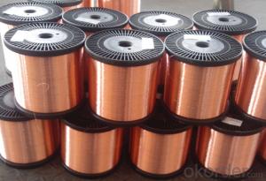
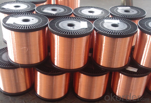
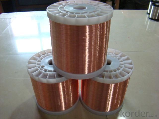
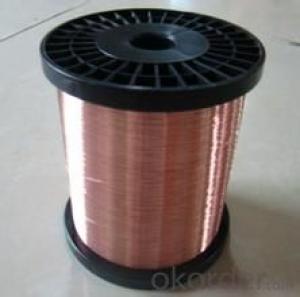
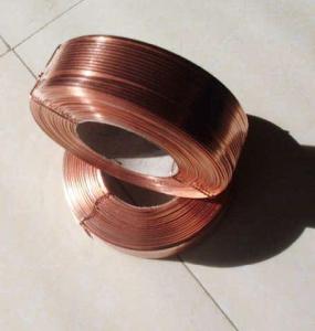
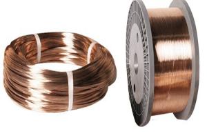
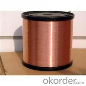
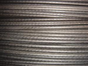
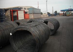
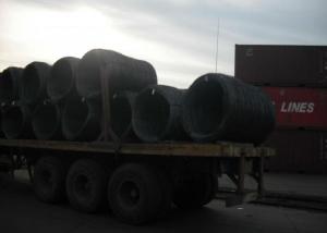
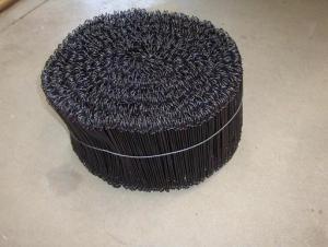
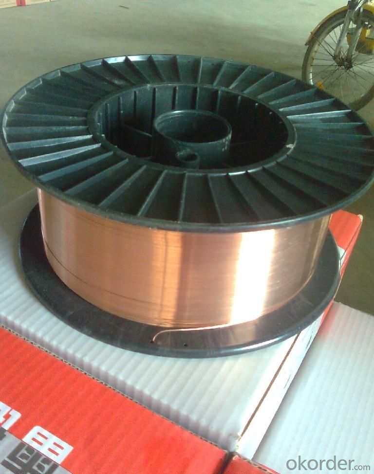
Physical Coating CopperClad Aluminum Wire
- Loading Port:
- Guangzhou
- Payment Terms:
- TT OR LC
- Min Order Qty:
- 500 kg
- Supply Capability:
- 100000 kg/month
OKorder Service Pledge
OKorder Financial Service
You Might Also Like
1. Product Description:
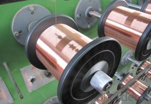
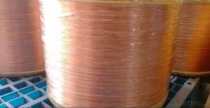
Cooper – clad aluminum wire is formed by the aluminum-cored wire and the copper layer closely covered outside, at the same time, it has the advantage of good electrical conductivity of copper and light weight of aluminum, it is the preferred material of the conductors in the coaxial cable and the electrical wires and cables in the electrical equipment.
Widely used in electrical tools, ballasts, automotive electronics, refrigerator and air conditioner compressor motors, television sets, electric stove, microwave ovens, various transformers, and other kinds of electronic coil motors, electrical appliances, electronic component ,instrument windings ,communication equipment ,step motors , Refrigerator rating compressors, Ballast , Home appliance product. High heat-resistant and electrical.
2. Product Characteristic:
(a) Good conductivity of copper,light weight of aluminum
(b) High signal transmission property
(c) Direct soldering, good colorability , high adhesiveness
(d)thermal stability . High thermal endurance. High temperature softening breakdown
(h)HF-resistance, solvent resistance and chemical property resistance to winding damage
3.Specification:
Copper Volume | Copper in volume | Copper in mass % | Density % (g/cm3) | Max. DC resistivity Ω.mm2/m(200c) | Tensile strength | Enlongation |
CCA-10% | 8~<13 | 27 | 3.32 | 0.02733 | 150MP | ≥10% |
CCA-15% | 13-17 | 37 | 3.63 | 0.252-0.026 | 160MP | ≥11% |
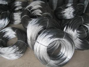
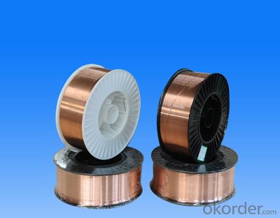
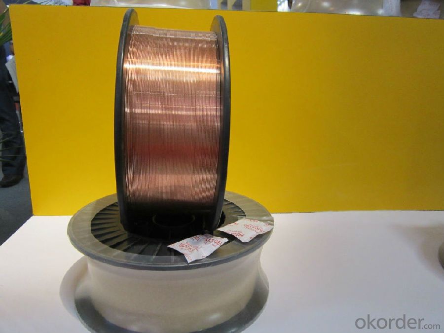
4. Reference Picture
- Q: I am looking for some answers when it comes to soldering wires. Lets say I am using 6 to10 (22 AWG 2 conductor wires) and I want to solder those to 1 wire for power source and 1 wire for ground. Now lets say soldering 10 wires to 1 wire for power and 10 wires to 1 wire for ground. All the wires are the same AWG guage. Now that the wires are twisted together and soldered to the hot and ground source, by doing this will I actually make a resistor or change the amperage or reduce the voltage by soldering so much wires together to a 1 wire source? The power source I am using is 12 Volts. If anyone knows of anywhere I can find this information online, etc, I would appreciate it.
- it will effect the voltage because it will split the power 10 defferent ways. i dont know any website that will tell you this but there is a tester that you can get to test the voltage. thats how i found out.
- Q: I wired an outdoor lamp-post. I tested it before wiring it to the fuse box...and if I touch the lamp-post I feel the current (a slight shock). I will be using a ground fault breaker....so I assume if I wire it to that I am going to loose the connection. Any thoughts on what is wrong?
- In addition to the answer Paul gave, check the wiring that the white wire is the neutral or common wire and that it goes to the shell side of the lamp holder. A few years ago, I had a similar problem, when all of the checks were made, the panel was wired with the black wires on the neutral buss. Hence all of the devices were wired backwards. Call a qualified professional electrician to do the work.
- Q: Blue and white wires contain insulated strands and red wire has a bundle of non-insulated strands. How are the two types of wires (insulated and non-insulated strands) used in homes (i.e. what are they used for?).
- that query is slightly large. It quite relies upon on what you're utilising the cord for. even if that is carrying electric powered contemporary, the insulation will prevent unintentional contact with the present, which could effect in damage to someone or unintentional contact with floor, that could want to effect in failure of the circuit. if you're doing something else, like making a bucket deal with out of cord or utilising it to tie something on your vehicle, the insulation would grant you with a better acceptable grip, which may be better secure in its own correct.
- Q: Okay so I just finished replacing a stolen car radio, but I think I messed up the wiring... When I turn off the car the radio doesn't seem to save the presets I had... it resets the whole stereo... I think it has something to do with the wiring I did... When I installed the radio there were two 12+ volt wires... One said 12+ volt constant and was yellow, and the other said 12+ volt switch and was pink... Problem was when I wired only the yellow one the car stereo wouldn't work, so I tried the pink one and that didn't work.. SO thinking I was clever I wired both to the 12+ volt and VOILA the radio turned on... Problem is I don't think that's how I was supposed to wire it... I have a '97 Honda accord Ex and I don't know if that's what I was supposed to do... :#92;
- yes you wired it wrong. If you were hooking these wires up directly to the car wires, then you could have shorted something out or caused further damage to the vehicle electrical system. If you were using a wiring harness, which i highly recommend, then you need to make sure the radio has ground switched and constant power. If it doesn't have one of these three, it will NOT turn on. Now i'd have to look at exactly how you hooked up the wires to see what went wrong. like i said if you didnt use a wiring harness there is a good chance you could have blown a fuse or screwed something else up. When not using a wiring harness the wires do not match color to color.
- Q: like lets i want to want to connect my speaker wires with other wires can i use elmer glue so that it sticks and will the wires still work?
- Nope - Elmer's glue won't conduct electricity. You can simply twist them together and wrap some electrical or plastic tape around them. You won't get a good connection, but it's usable. The easiest way is to buy some twist-on wire nuts to connect the wires.
- Q: How do you attach light wires to boat trailer frame?
- The colour code for trailers is as follows, white-ground, brown-running, yellow-left turn, green-right turn and blue would be for trailer brakes if your trailer has them or auxiliary. If your adapter (on the Dakota) is hooked up properly those are the wire colours that run from your vehicle into the trailer lights and the signal lights will also be the brake lights.
- Q: i have some blue speaker wire in my wiring kit for my subs but where do i start it out from my head deck when i start to wire it all together.
- you connect the blue wire to either your power antenna turnon wire or a separate amp turnon lead. Newer decks might have a separate lead for the amp turnon. Your main power wires goes directly to your battery the blue turnon wire actually turns the amp on when you turn on the radio.
- Q: I bought a bathroom vent fan today, the one that was in there hasnt worked since we bought the house. Anyways, i have a black wire, and a white wire coming from the light switch on the wall ran up to the ceiling where the fan is, and a black, white, and GREEN comin off the new fan i bought. Do i need to get in the attic and run a ground wire from outlet to fan? Or are the black and white good enough? The old fan didnt have a ground wire, just the other 2. Any info is greatly appreciated. Thanks
- Green wire should be screwed into the inside of the receptacle box or pigtailed to the bare copper wire in the back of the box. If neither a bare wire or a green screw is present, call an electrician to run proper wiring to the box
- Q: I understand that in a plug you have the earth wire, live wire and neutral wire. But what is the individual job of these wires?? I know how to wire a plug, i just want to know the individual job of each wire. This is not homework, this is something iam teaching myself.Thanks.
- The typical U.S. power distribution system has two hot wires coming into your electric panel, plus a neutral wire. The neutral wire is grounded to earth ground, as is the protective green earth wire. An outlet, carrying 110 volts from one of the hot wires (black), supplies current for the load and it flows back to the transformer on the pole normally via the neutral (white) wire to the center transformer (grounded) tap. The green protective wire does nothing in normal operation. However, should the appliance have a metal outer skin, and the machine develops a short, energizing the outer skin, it will flow through the green ground wire back to the transformer rather than through you and back to the transformer.
- Q: I bought a cheap amp wiring kit so the ground wire is not the same size as the power wire but my friend gas me an extra piece of 8 gauge wire same as mine if i put both of these to on at the same time would it help out any? also he gave me some audio cable like the wires inside are twisted to gather the box says it gives you better sound quality would they make a difference in sound that the one's i have on there know?Thanks
- NO, you need to buy thicker wire because electricity follows the path of least resistance which means if one of the wires is 1/8 of an inch longer than the other, that is the wire the most electricity will flow through, as far as the speaker wire it wont make a difference unless it is thicker than what you already have installed (its very hard to tell the difference in sound quality even with very high quality speakers
Send your message to us
Physical Coating CopperClad Aluminum Wire
- Loading Port:
- Guangzhou
- Payment Terms:
- TT OR LC
- Min Order Qty:
- 500 kg
- Supply Capability:
- 100000 kg/month
OKorder Service Pledge
OKorder Financial Service
Similar products
Hot products
Hot Searches
Related keywords
