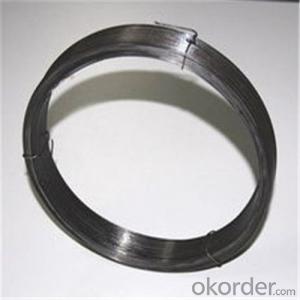
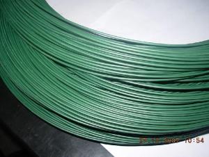
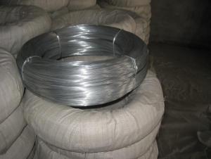
insulated galvanized steel wire
- Ref Price:
-

- Loading Port:
- China Main Port
- Payment Terms:
- TT OR LC
- Min Order Qty:
- -
- Supply Capability:
- 2000km m/month
OKorder Service Pledge
OKorder Financial Service
You Might Also Like


Quick Details
Place of Origin:Jiangsu, China (Mainland)
Model Number:7-conductor
Insulation Material:F46
Type:Low Voltage
Application:oilfield, well logging, oil exploration
Conductor Material:Copper
Jacket:steel wire
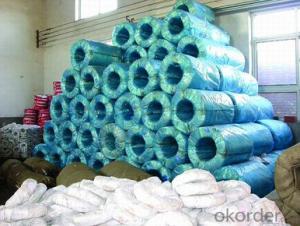
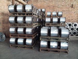
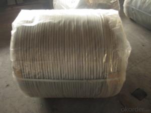
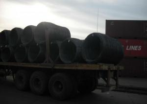
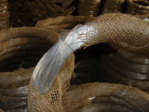
Packaging & Delivery
| Packaging Details: | Iron pan, wooden tray or according to customer's requirement. |
|---|---|
| Delivery Detail: | 30 days after payment |
Specifications
well logging cable
a. Quick delivery
b. Competitive price with high quality
c. Free samples
d. Expert in cable and wire
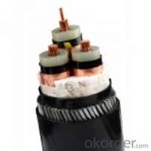
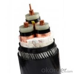
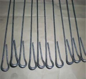
7-conductor fluoroplastics F46 insulated double-deck steel thread armored oilfield well logging cable for oilfields
1. Product Standard
The product is manufactured according to the standard of SY/T6600-2004.
2. Application
The product is applicable to all types of oil and gas well logging, perforation, coring and paraffin oil wells, viscosity, pour point and so on. It’s such kind of oil field exploration armored steel cable which could bear all the above mentioned mechanical load.
3. Operating Characteristics
a.The lowest temperature that cable could work should not be lower than-30°C.
b.Max temperature is 232°C for short period (2h maximum duration each time).
c.Minimum bending radius is 30 times of cable diameter.
CONSTRUCTION DESCRIPTION:
Copper Construction: | 7×0.0129’’ | 7×0.33 mm |
Plastic Type: | PP |
|
Insulation Thickness: | 0.0936’’ | 2.38 mm |
Number and Size of Wires: |
|
|
Inner Armor: | 16×0.05925” | 16×1.505 mm |
Outer Armor: | 20×0.06575” | 20×1.67 mm |
Average Wire Breaking Strength: | ||
Inner Armor: | 747 lbs | 3325 N |
Outer Armor: | 920 lbs | 4094 N |
CABLE CHARACTERISTICS:
PHYSICAL:
Cable Diameter: | 0.520’’±0.0039’’ | 13.20 mm ±0.10 mm |
Cable Weight In Air: | 473 lbs/Kft | 704 Kg/Km |
Temperature Rating : | 450 °F | 232 °C |
MECHANICAL:
Cable Breaking Strength: | 24720 lbs | 110 KN |
Minimum Sheave Diameter: | 23.5’’ | 590 mm |
Cable Stretch Coefficient: | 0.714 ft/Kft/Klbs | 0.80 m/Km/5KN |
ELECTRICAL:
Voltage Rating: | 1200 VDC | 1200 VDC |
Insulation Resistance: | 50000 MΩ·Kft | 15000 MΩ·Km |
DC Resistance @ 20°C | 10 Ω/Kft | 33 Ω/Km |
Cap Typical @ 1 KHz | 40 Pf/ft | 130 Pf/m |
- Q: What is the best brand of wire to use for getting power to my amp?
- Monster cable 10 awg
- Q: i hav a 2000 explorer and just got a new head unit and bought a wiring harness to hook it up. on the wiring harness that's supposed to be plugged in to the truck there are 2 illumination wires, 1 of them is the illumination ground .Out of my new stereo there is only the illumination wire not an illumination ground wire. where do I put the illumination ground ? also i have 2 ground wires coming from my new deck 1 is 12v ground and the other is a chassis ground can i just hook them together?
- workin for best answer 2000 Ford Explorer Car Stereo Radio Wiring Diagram. Car Radio Constant 12V+ Wire: Light Green goes to your yellow deck wire Car Radio Switched 12V+ Wire: Yellow/Black goes to your red deck wire Car Radio Ground Wire: Black goes to your black ground wire Car Radio Illumination Wire: Light Blue/Red goes to your illumination wire Car Radio Dimmer Wire: N/A Car Radio Antenna Trigger Wire: Blue Car Radio Amp Trigger Wire: N/A if u have a amp this goes to your blue remote wire Front Speakers Size: 5″ x 7″ Front Speakers Location: Doors Left Front Speaker Wire (+): Orange/Light Green Left Front Speaker Wire (-): Light Blue/White Right Front Speaker Wire (+): Dark Green/Orange Right Front Speaker Wire (-): White/Light Green Rear Speakers Size: 5″ x 7″ Rear Speakers Location: Rear Door Left Rear Speaker Wire (+): Gray/Light Blue Left Rear Speaker Wire (-): Tan/Yellow Right Rear Speaker Wire (+): Orange/Red Right Rear Speaker Wire (-): Brown/Pink hope this helps
- Q: If you put clay over wire and bake it would the wire melt and ruin the sculpture?Details on wire:I'm not sure what kind of wire it is but it says Bright Floral Wire..Wire is silverDetails on Clay:Again, im not sure what clay...its from polyform products and it says Premo Sculpey so im guessing Polymer? :#92;Clay is Black.Bakes for 275F (130C)30 minutes per/par/por1/4 in (6mm)
- No the wire won't melt - besides fuse wire or solder, the lowest common melting point wire is aluminum and it melts at over 1200F Floral wire is usually steel and melts at more like 3000F, but even if it were copper, that melts at about 1900F The real problem with using wire in polymer sculptures is that when the clay shrinks in baking it may pull apart along the wire or that you may make parts of your sculpture thin (like legs or arms) and part thick (like body or head) and thick clay tends to crack - so these parts need to be hollow, which is why people talk about crumpling heavy duty aluminum foil as a core, so the clay is more uniform in thickness all over. Don't forget to have an oven thermometer for accurate temperature checking - don't trust the knob setting on the oven.
- Q: How do you wire a 2 wire smoke detector directly to an alarm (no panel). The terminals are numbered 1,2,3,4 and the instructions say that 1 is for DC+ and 2 is for DC-. How do I wire an alarm so when the detector senses smoke, the alarm goes off? Thank you.
- That's DC alarm ,mean you should connected in to 9 volt battery. There are 4 wire alarms that are design for serial alarms. Smoke alarm it's required ,without AC power act and also With AC power act .mean if AC power go off then system will respond on battery power .
- Q: I am building an ice chest boombox and want to wire a toggle (on/off) switch to turn the amp on and off....the amp is wired directly to the battery....my question is that I am using 6 gauge wire....but can't find any female spade connectors that are 6 or even 4 gauge to hook to the terminals on the switch.....what is a simple way to do this....am I going to have to solder the wire straight to the terminals?
- Why not wire the toggle switch into the remote + wire? The one that turns the amp on and off with the head unit. 7/5/2013**** Leave the power supply wire alone. The thick 4 gauge wire that runs from the battery directly to the amp, leave it alone, don't put a toggle switch inline on that wire. Instead there's a wire from your head unit (or ignition) that runs to your amp, it turns on the amp when the head unit turns on or your ignition key is in the on position. It's usually 16 or 14 gauge. That's the wire where the toggle switch belongs. Look at your amp, this wire I am speaking of is probably labeled remote+ or ign or something like that and it's usually located next to your power and ground connections on the amp.
- Q: Hi,I'm trying to install a ceiling light with a 3 wire configuration (white, black, ground) into a wire configuration of 4 wires (white, red, black, ground). This is configured for two on/off switches.So far, I have white to white, black to black, and ground to ground with the red capped off. This works with one switch perfectly, however when I hit the other switch, the circuit breaker blows.Please help, and thank you!
- A circuit consists of two conductors not counting the green/bare, but can have more than two. Also a circuit can branch off and energize other things. Thus you have branch circuits. The ceiling box fan probably is a branch circuit consisting of two or three maybe four conductors i.e., black, red, white and green/bare. A ceiling fan will pull a load/current of usually 2 amps but can be a lot more. A 60watt incandescent light bulb pulls 1/6 of an amp, or 4 60watt bulbs is around 2amps. By and far the amount is very low considering most general lighting circuits can handle up to 20amps without any problems.
- Q: Ok, bought this mower at an estate auction for next to nothing. It looks like its never been used. Previous owner ripped out all the wires to the ignition switch so it wouldn't sell I guess. It's the craftsman lt 1500. Model number 247.288812. It has the 17.5hp bs motor in it. Does anyone know the correct way the wires go to the switch? There are 3 red wires so its a bit unlike what im used to. Thanks in advance!
- On my sears mower with an electric clutch the switch is wired like this. G terminal is a black wire to ground. B terminal is a red wire to the ammeter. S terminal is a white wire to a safety switch. M terminal has two black wires one to the ignition coil and the other to a safety switch. L teminal is a red wire to the alternator and a red wire to the PTO switch.
- Q: How can I make a wire dress form?
- Use chicken wire for the molding of the body. Make tube of the wire the width of the hip and bust area. Hook it together by intertwining the ends. All you have to do is mesh the wire, where you want it smaller and mold the bust to the size you want. After you mold it like how you want it, cover it with a single knit material. Then make a wooden stand to hold it at the height you want. It is very simple to do. I made a 7 foot hat that way to fit on a car for a parade.
- Q: I'm trying to hook up my second phone line. I have a red, green and yellow wire in the cable, but no black wire. Is there a reason for this? And what can I do to get the second line up and running? thx
- the wire you have is designed for 1 line only. Back in the day the yellow wire was used to carry ground because ground was necessary for old circuits. Ground is no longer needed so in order to get two lines you need at least a two pair wire (meaning four wires) you might have to run a new wire unfortunately or just keep that one and run another to separate jack.
- Q: wic iring codes for turner plus three wired to uniden washington cb radio
- I love wiring questions :) do you want to use the PTT? If yes you can assume it is a switch and solder it inline with the lead the other end (after the switch would be connected to the lead end of the 1/4 if you have a pigtail 1/4 then this would be the insulated wire, the ground would simply connect to the uninsulated wire if you are actually using a do it yourself 1/4 plug then the same rules apply only you are soldering to the terminal inside the plug sleeve rather then to bare wires (I always prefer this its cleaner). Please Note: The PTT switch will cause a loud pop when it is engaged and released on a Hi Gain guitar amp and sometimes this can damage the speakers as well as delicate internal components so do this of coarse at your own risk.
Send your message to us
insulated galvanized steel wire
- Ref Price:
-
- Loading Port:
- China Main Port
- Payment Terms:
- TT OR LC
- Min Order Qty:
- -
- Supply Capability:
- 2000km m/month
OKorder Service Pledge
OKorder Financial Service
Similar products


Hot products

Hot Searches
Related keywords

