

I Beam Steel YBT24 for Mining Applications with Large Sizes
- Ref Price:
-

- Loading Port:
- China main port
- Payment Terms:
- TT or LC
- Min Order Qty:
- 25 m.t.
- Supply Capability:
- 10000 m.t./month
OKorder Service Pledge
OKorder Financial Service
You Might Also Like
1. Structure of I Beam Steel YBT24 for Mining Applications with Large Sizes Description:
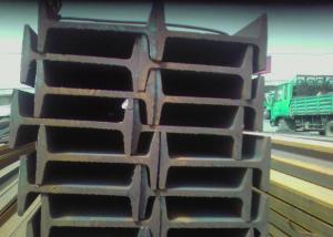
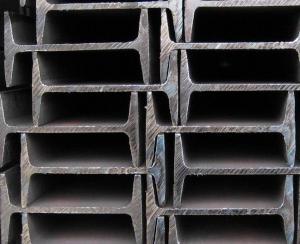
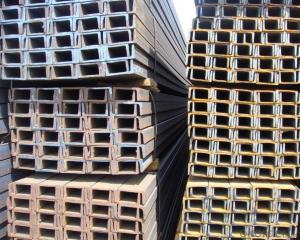
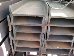
I beam steel YBT24 for mining applications with large sizes is a beam with an I-shaped cross-section. The horizontal elements of the "I" are known as flanges, while the vertical element is termed the "web". I beam steel YBT24 for mining applications with large sizes is usually made of structural steel and is used in construction and civil engineering. The I beam steel YBT24 for mining applications with large sizes resists shear forces, while the flanges resist most of the bending moment experienced by the beam. I beam steel YBT24 for mining applications with large sizes theory shows that the I-shaped section is a very efficient form for carrying both bending and shears loads in the plane of the web.
2. Main Features of I Beam Steel YBT24 for Mining Applications with Large Sizes:
• Grade: Q235
• Type: Mild carbon steel
• Deflection: The stiffness of the I-beam will be chosen to minimize deformation
• Vibration: The stiffness and mass are chosen to prevent unacceptable vibrations, particularly in settings sensitive to vibrations, such as offices and libraries.
• Local yield: Caused by concentrated loads, such as at the beam's point of support.
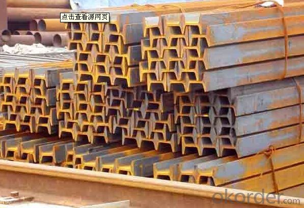
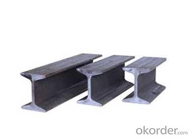
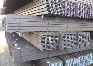
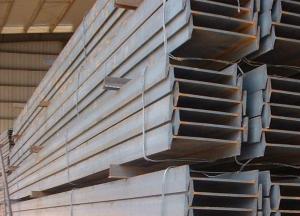
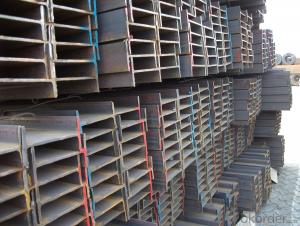
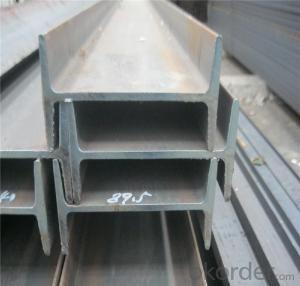
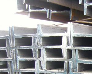
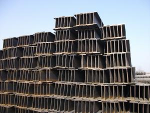
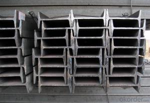
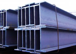
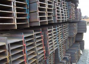
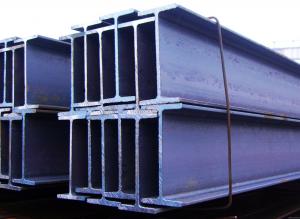
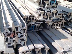
3. I Beam Steel YBT24 for Mining Applications with Large Sizes Images:


4. I Beam Steel YBT24 for Mining Applications with Large Sizes Specification:
Mechanical Properties | Grade | Steel diameter(mm) | |||
≤16 | 16~40 | 40~60 | 60~100 | ||
Yield Point Δs/MPa | Q195 | ≥195 | ≥185 | - | - |
Q235 | 235 | 225 | 215 | 205 | |
Tensile Strength | Q195 | 315~390 | |||
Q235 | 375~500 | ||||
Elongation δ5% | Q195 | ≥33 | ≥32 | - | - |
Q235 | 26 | 25 | 24 | 23 | |
5. FAQ
We have organized several common questions for our clients,may help you sincerely:
①Is this product same as W beam?
In the United States, the most commonly mentioned I-beam is the wide-flange (W) shape. These beams have flanges in which the planes are nearly parallel. Other I-beams include American Standard (designated S) shapes, in which flange surfaces are not parallel, and H-piles (designated HP), which are typically used as pile foundations. Wide-flange shapes are available in grade ASTM A992,[4] which has generally replaced the older ASTM grades A572 and A36.
②How to inspect the quality?
We have a professional inspection group which belongs to our company. We resolutely put an end to unqualified products flowing into the market. At the same time, we will provide necessary follow-up service assurance.
③Is there any advantage about this kind of product?
Steel I beam bar IPE has a reduced capacity in the transverse direction, and is also inefficient in carrying torsion, for which hollow structural sections are often preferred.
- Q: There are no columns in the middle of the workshop of 37 meters span. How much I-beam do I need?
- H type I-beam is also called wide flange I-beam, HW, HM, HN originated from European standards, HEB is the German standard of I-beam, of which HW, HN I-beam has been widely used in our country and production. HEA HEB HEM will be seen on many German designs and is hard to buy on the domestic market. In the domestic steel structure engineering, if the quantity is few, then may use the specification steel plate to carry on the welding splicing. In the case of large quantities, it is usually considered to use mechanical properties comparable to those of HW and HN steel.
- Q: How do steel I-beams perform in terms of vibration control?
- Steel I-beams are widely recognized for their exceptional strength and load-bearing capabilities. However, when it comes to vibration control, their performance may vary depending on several factors. Firstly, steel I-beams have a natural frequency at which they tend to vibrate. This natural frequency is determined by their dimensions, material properties, and overall structural configuration. If the excitation frequency of the vibration matches the natural frequency of the beam, resonance can occur, leading to increased vibrations and potentially compromising the structural integrity. To mitigate vibrations in steel I-beams, several strategies can be employed. One common approach is to increase the stiffness of the beam by adding additional steel plates or braces. This increases the natural frequency of the beam, making it less susceptible to resonance with external vibrations. Additionally, damping systems can be incorporated into the design of steel I-beams to dissipate energy and reduce vibrations. These systems typically consist of damping materials, such as viscoelastic polymers or rubber pads, that absorb and dissipate vibrational energy. It is worth noting that the performance of steel I-beams in terms of vibration control can also be influenced by the surrounding structural elements and the overall design of the building or structure. For example, the presence of other damping elements, such as tuned mass dampers or base isolators, can further enhance the vibration control capabilities of steel I-beams. In summary, steel I-beams have inherent natural frequencies that can affect their performance in terms of vibration control. By increasing stiffness and incorporating damping systems, the vibrations can be mitigated and the overall structural integrity can be maintained. However, it is crucial to consider the specific design requirements and surrounding structural elements to optimize the vibration control performance of steel I-beams.
- Q: Can Steel I-Beams be used for wastewater treatment plants?
- Yes, steel I-beams can be used for wastewater treatment plants. Steel I-beams are commonly used in the construction industry due to their strength and durability. In wastewater treatment plants, I-beams can be utilized for various purposes such as supporting heavy equipment, constructing walkways and platforms, and providing structural support for tanks and other infrastructure. The corrosion resistance and load-bearing capacity of steel I-beams make them suitable for withstanding the harsh and corrosive environment found in wastewater treatment plants. Additionally, steel I-beams can be easily fabricated and installed, making them a cost-effective and efficient choice for wastewater treatment plant construction.
- Q: Are steel I-beams resistant to hurricanes or cyclones?
- In hurricane or cyclone-prone areas, steel I-beams are known for their exceptional resistance to these natural disasters. These structural components are meticulously designed to withstand the immense forces associated with such extreme weather conditions. Due to their robustness and rigidity, steel I-beams have the capacity to endure strong winds, torrential rain, and even airborne debris. Moreover, their remarkable ability to evenly distribute loads plays a crucial role in minimizing the risk of structural failure during these severe climatic events. All in all, opting for steel I-beams is a dependable way to ensure the safety and structural integrity of buildings in regions susceptible to hurricanes or cyclones.
- Q: Can steel I-beams be painted or coated after installation?
- Yes, steel I-beams can be painted or coated after installation. Painting or coating the steel I-beams is a common practice to provide protection against rust and corrosion, enhance their appearance, or to match the surrounding environment. The painting or coating process involves cleaning the surface of the I-beams to remove any dirt, grease, or loose material, followed by applying a primer to ensure proper adhesion of the paint or coating. Once the primer is dry, the desired paint or coating is applied using techniques such as brushing, spraying, or rolling. It is important to use high-quality paint or coating products that are specifically formulated for steel surfaces, as they provide excellent durability and resistance to weathering. Regular maintenance and periodic repainting or recoating may be necessary to ensure the continued protection and aesthetic appeal of the steel I-beams.
- Q: How are steel I-beams lifted into place during construction?
- Steel I-beams are typically lifted into place during construction using heavy-duty cranes. These cranes are specifically designed to handle the weight and size of the beams. The process begins by positioning the crane near the area where the beam needs to be installed. The beam is then attached to the crane using steel cables or chains, ensuring that it is securely fastened. Once the beam is properly attached, the crane operator carefully lifts it off the ground, taking into account the weight and balance of the beam. The crane is controlled by the operator who maneuvers it into the correct position and then lowers the beam into place. During this process, it is important to ensure that the beam is aligned correctly with other structural components to maintain the structural integrity of the building. The crane operator may rely on the assistance of signalers or spotters on the ground to guide the positioning of the beam. In some cases, multiple beams may need to be lifted and placed one after the other to form a complete structure. This requires careful coordination between the crane operator and the construction team to maintain safety and efficiency. Once the beam is in its final position, it may be secured further using bolts or welds to connect it to other structural elements. These connections are crucial for ensuring the stability and strength of the overall structure. Overall, the lifting of steel I-beams during construction requires the expertise of skilled crane operators and a well-coordinated effort by the construction team. The use of cranes allows for precise positioning of the beams, ensuring that they are installed safely and accurately.
- Q: What are the common welding techniques used for steel I-beams?
- The common welding techniques used for steel I-beams include shielded metal arc welding (SMAW), gas metal arc welding (GMAW), and flux-cored arc welding (FCAW). These methods ensure strong and secure welds between the different sections of the I-beams, allowing them to withstand heavy loads and maintain structural integrity.
- Q: Can steel I-beams be used for rooftop equipment supports?
- Yes, steel I-beams can be used for rooftop equipment supports. Steel I-beams are commonly used in construction for their high strength and load-bearing capabilities. They provide a sturdy and durable option for supporting heavy equipment on rooftops. Additionally, steel I-beams can be easily customized and fabricated to meet specific requirements, making them a versatile choice for rooftop equipment support systems. However, it is important to ensure that the structural integrity of the building can handle the additional weight and that proper engineering calculations are performed to determine the appropriate size and configuration of the steel I-beams to safely support the rooftop equipment.
- Q: What are the fire protection measures required for steel I-beams in certain applications?
- Fire protection measures for steel I-beams in certain applications are necessary to ensure their structural integrity and prevent collapse during a fire. Steel is a strong and durable material, but it can lose its load-bearing capacity when exposed to high temperatures. Therefore, fire protection measures are essential to maintain the structural stability of steel I-beams and protect the overall building from fire-related hazards. One common fire protection measure for steel I-beams is the application of fire-resistant coatings or intumescent paints. These coatings are specifically designed to expand and form a protective layer when exposed to heat. They act as a barrier, reducing the rate at which heat is transferred to the steel, thereby delaying its temperature rise. This delay allows more time for occupants to safely evacuate the building and for firefighters to control the fire. Another effective method is the use of fire-resistant insulation materials, such as mineral wool or gypsum-based boards. These materials are installed around the steel I-beams to provide thermal insulation, preventing the transfer of heat from the fire to the steel. The insulation materials also absorb heat energy, thereby reducing the overall temperature rise of the steel I-beams. In certain applications, the use of fireproof enclosures or fire-rated barriers is required to protect steel I-beams. This can involve encasing the beams in fire-resistant materials or constructing fire-rated walls or ceilings around them. These enclosures or barriers create a physical barrier between the fire and the steel, preventing direct exposure to high temperatures. Additionally, in buildings with sprinkler systems, the presence of properly designed and maintained sprinklers can significantly enhance fire protection for steel I-beams. Sprinklers can suppress or extinguish a fire, limiting its spread and reducing the impact on structural components like steel I-beams. It is important to note that fire protection measures for steel I-beams may vary depending on the specific building codes, regulations, and fire safety standards applicable in a particular jurisdiction. Consulting with fire protection engineers or professionals knowledgeable in local regulations is crucial to determining the appropriate fire protection measures required for steel I-beams in certain applications.
- Q: The bridge pier cap beam on the I-beam have what use? What points should we pay attention to?
- The lower part of the structure foundation and pile foundation, beam, pier, beam, beam, bearing pad stone, block, abutment bearing pad stone, all under the block structure and the corresponding soilThe superstructure is prefabricated and installed with beams (plates) prefabricated and installedThe upper structure is filled with a wet joint or a joint between the pier top, the cast-in-place continuous section and the beam (slab)The overall bridge deck and ancillary works include the installation of bearings, bridge deck pavement, inner and outer guardrail expansion jointsProtection works include abutment, cone slope, masonry and filling
Send your message to us
I Beam Steel YBT24 for Mining Applications with Large Sizes
- Ref Price:
-
- Loading Port:
- China main port
- Payment Terms:
- TT or LC
- Min Order Qty:
- 25 m.t.
- Supply Capability:
- 10000 m.t./month
OKorder Service Pledge
OKorder Financial Service
Similar products
Hot products

Hot Searches
Related keywords

