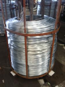
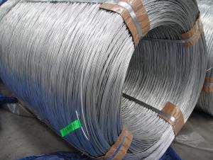
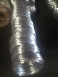
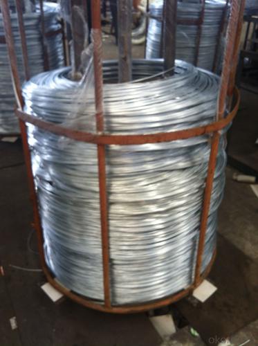
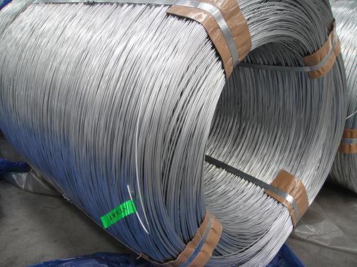
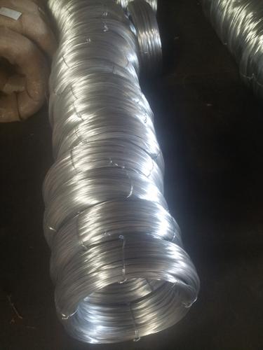
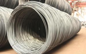
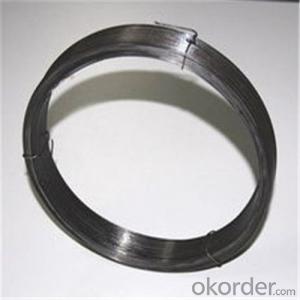
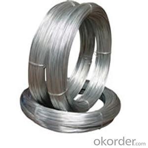
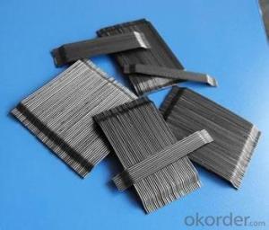
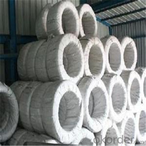
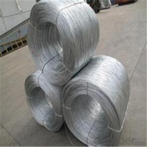
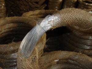
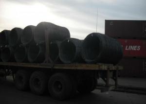
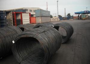
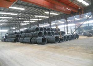
Hot Dip Galvanised Iron Wire
- Loading Port:
- China Main Port
- Payment Terms:
- TT OR LC
- Min Order Qty:
- -
- Supply Capability:
- -
OKorder Service Pledge
OKorder Financial Service
You Might Also Like
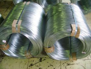
Hot Dip Galvanized Steel Wire
(1) Quality : Meet GB/T 343 standard and other requirements of relevant standards .
(2) Zinc Coating: Meet GB/T 15393 standard and other requirements of relevant standards .
(3) Raw Material : Wire rod ——1006 , 1008 , 1018 , Q195 , etc, and zinc with 99.995% purity.
(4) Tensile Strength Range
Size (mm) | Tensile Strength (mpa) |
0.15-1.60 | 290-550 |
0.65-1.60 | 400-550 |
1.61-6.00 | 400-1200 |
(5) Application : Used in wire mesh , artware , metal hose , binding for agriculture and construction , etc.
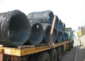
(6) Packing
Size (mm) | Coil Size | Spool Packing | Big Coil Packing | |
ID (mm) | OD (mm) | |||
0.15-0.26 | 6 inch | 1-14kg/spool |
|
|
0.27-0.60 | 8 inch | 1-100kg/spool |
|
|
0.61-1.60 | 12/14/16 inch | 1-100kg/spool | 250-400 | 400-770 |
1.61-6.00 |
| 14-500kg/spool | 450 | 800 |
508 | 840 | |||
(7) Zinc Coating
Meet GB/T 15393 standard.
Size (mm) | Weight of Zinc-Coating ( g/m2 ) | |||||||
A | AB | B | C | D | E | F | ||
A1 | B2 |
|
|
|
|
|
| |
≤0.25 |
|
| 30 | 20 | 18 |
|
|
|
>0.25-0.40 |
|
|
| 30 | 25 | 20 |
|
|
>0.40-0.50 |
|
|
|
| 30 | 20 |
|
|
>0.50-0.60 |
|
|
|
| 35 | 20 |
|
|
>0.60-0.80 | 120 | 110 |
|
| 40 | 20 |
|
|
>0.80-1.00 | 150 | 130 |
|
| 45 | 25 |
|
|
>1.00-1.20 | 180 | 150 |
|
| 50 | 25 |
|
|
>1.20-1.40 | 200 | 160 |
|
| 50 | 25 |
|
|
>1.40-1.60 | 220 | 180 |
|
| 50 | 35 | 30 |
|
>1.60-1.80 | 220 | 180 |
|
| 70 | 40 | 30 |
|
>1.80-2.20 | 230 | 200 |
|
| 80 | 50 | 40 |
|
>2.20-2.50 | 240 | 210 |
|
| 80 | 55 | 40 |
|
>2.50-3.00 | 250 | 230 |
|
| 90 | 70 | 45 |
|
>3.00-4.00 | 270 | 250 |
|
| 100 | 85 | 60 | 30 |
>4.00-5.20 | 290 | 270 |
|
| 110 | 95 | 70 | 40 |
>5.20-6.00 | 290 | 270 | 245 |
| 110 | 100 | 80 | 50 |
- Q: im assuming red to red and black to black? but then what about the extra green and white wires in the iphone cable? where do they go?
- if you have a multimeter or a volt meter, ascertain the voltage at the amp. If youre interpreting 12V then the fuse for yourchronic furnish is sturdy, if no longer, replace the fuse. Then ascertain you have sturdy grounds (naked metallic, no painted surfaces, secured/bolted tight) If these are ok ascertain your distant cord. Its frequently a skinny blue cord as soon as you purchase the kits. it fairly is the on/off swap. if you have a manufacturing unit radio, then your distant replaced into hooked to an adjunct that good factors 12V at an analogous time as your motor vehicle key turns the upload-ons on (acts as a swap) like a cigarette lighter. If that cord is linked wisely to the amp yet its no longer exhibiting 12V, then its maximum possibly that the fuse for that distinctive accessory is out. replace it. If none of these solves the priority then the priority is with the amp itself. Have it appeared at. despite the fact that it may no longer be the battery because of the actual fact in case your battery replaced into undesirable, it wouldnt influence purely your amp, yet every little thing else on your motor vehicle.
- Q: can a positive wire connect a negative and positive terminal together, or can a negative wire connect a positive and negative terminal together? This is regard to speakers in a guitar speaker cabinet. using rca speaker wire which is two wires that can be separated. One is positive and the other negative. If you are only using one half of the wire to wire two speakers in series does it matter if it is the positive(the side with the white stripe) or negative one since wiring in series is positive terminal to negative terminal.
- effective and detrimental keep on with to DC in elementary words, together with a battery or a skill grant. both of both might want to be grounded, or neither might want to be grounded. For AC, which varies between effective and detrimental voltages many circumstances per 2d, the words effective and detrimental are literally not used. instead, for an AC skill distribution device together with at your position of residing, you've a warm and impartial and a floor twine. The impartial is linked to floor at one element and is the go back for the warm, which has a voltage on it that varies between effective and detrimental voltages many circumstances per 2d. the floor twine is for safe practices. .
- Q: Where is itI have a 1996 Honda Accord with a pioneer deh-p6400 head unit. I tried to install an amp. Held the ground to soem metal and tried to get it to turn on. I tried the power antennae wire and it didnt' work. Nothing seems to work. I dont want to splice any wires or anything
- The remote wire is the blue/white wire. The power antenna wire(blue) only has current when the tuner is being used therefore your amp would only work with the radio and nothing else.
- Q: I have a 1989 Nissan 240sx. Somehow the fan caught a hold of the wiring harness and tore all the wires. any idea how much it's going to cost?
- Buying a wiring harness will be prohibitive, and even transplanting one from a wrecking yard can be expensive. The harness can be repaired by splicing in pieces of wire where wire is missing and splicing together damaged pieces of wire. It is tedious but not particularly time consuming - I spliced in a section of harness after an engine fire in about 2 hours, working slowly.
- Q: the plug only has room for black,red,ground wire.. what do i do with the white wire
- If you have a dryer with a 3 prong cord you can combine the ground and white. Has been done for many decades if you use an older dryer.
- Q: i need thin insulated wire like this.
- It is called enamelled copper wire or copper winding wire. You will find it at Digi-key and other electronics retailers. Check OKorder as well. It comes in different gauges (thicknesses), the higher the number, the thinner the wire. I'd say the stuff he uses in the video is about 30 gauge.
- Q: I made a kill switch for my car. All I need to do now is cut the wire that goes into my engine control module and join it with the switch I made. Would it be fine if I just use wire nuts or some sort of tape to join the wires instead of soldering? The instructions say quot;Step 6: Attach the killswitch wires one to each side of the wire you just cut. Step 7: Tape up all new connection.quot;It says to tape the new connections, but should I use exactly?
- Solderless crimp-on butt connectors. $3.00 at Home Depot or Autozone.
- Q: is this a wire that like is the same as buying any other one?
- 8g might be a little overkill. A 10g 2 conductor wire should be sufficient for nearly any application. Here's a link with more than anyone ever needs to know about speaker wire:
- Q: How can u do a wire transfer? Is there anything extra that is needed to do this? Are you able to make a wire transfer from your home computer?
- Most people go to the bank and arrange for wire transfer from there. You will need to have the funds to wire, the account where you want it transfered to. it is possible, but it would have to be prearranged.
- Q: Two long straight parallel wires are 12 cm apart. Wire A carries 2.5 A current. Wire B's current is 3.7 A in t?Two long straight parallel wires are 12 cm apart. Wire A carries 2.5 A current. Wire B's current is 3.7 A in the same direction.1) Determine the magnetic field magnitude due to wire A at the position of wire BB = ? T2) Determine the magnetic field due to wire B at the position of wire A.B = ? T3) Are these two magnetic fields equal and opposite? Why or why not?4) Determine the force on wire A due to wire B, and the force on wire B due to wire A.
- (1) wire-A B = (uo)(I) / (2pi * r) B = (1.26E-6)(2.5) / (2pi * 0.12) B = 4.17E-6
Send your message to us
Hot Dip Galvanised Iron Wire
- Loading Port:
- China Main Port
- Payment Terms:
- TT OR LC
- Min Order Qty:
- -
- Supply Capability:
- -
OKorder Service Pledge
OKorder Financial Service
Similar products
Hot products
Hot Searches
Related keywords
