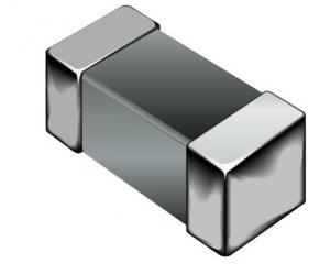
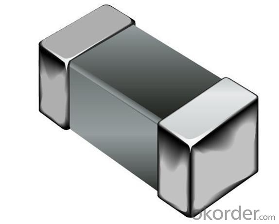
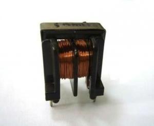
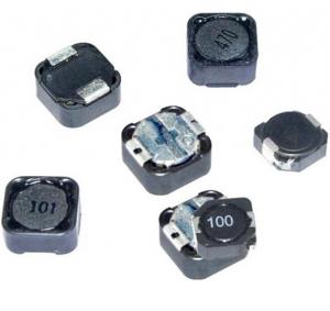
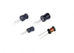
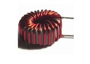
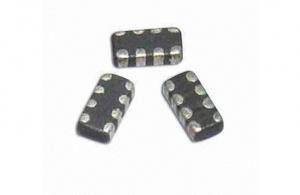
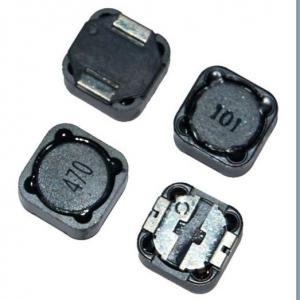
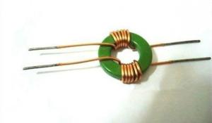
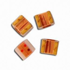
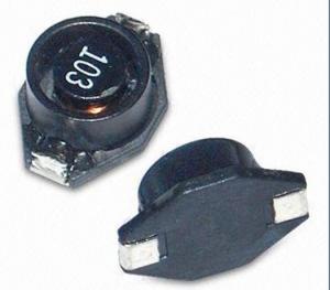
Ferrite Chip Inductors
- Loading Port:
- China Main Port
- Payment Terms:
- TT or LC
- Min Order Qty:
- 5000 Pieces pc
- Supply Capability:
- 50,000 Pieces per Day pc/month
OKorder Service Pledge
OKorder Financial Service
You Might Also Like
1.ferrite chip inductors
2.leaching resistant rerminations due to metal teb electrodes
3.Coils encapsulated in heat-proof
Features
1.Ferrite chip inductors
2.leaching resistant rerminations due to metal teb electrodes.
3.Coils encapsulated in heat-proof resin make high accurate
4.dimesions and resostant dimensionsand resostant to mechanical shock or pressure.
5.High resistance to heat and humidity.
Applications
Personal computers. Disk drives and comuter peripherals. Telecommunications devices. VCD, DVD and TV circuits,
Test equipment. Electronic control control boards for automobiles.
- Q: An LC circuit of a 4-mH inductor and a 200μF capacitor. If the maximum energy stored in the circuit is 10?4 J, what are the maximum charge on the capacitor and the maximum current in the circuit? What are the minimum values?Can someone please explain this in detail. thanks!
- The energy of the capacitor is stored as an electric field and is maximum when its fully charged. Once fully charged the capacitor then discharge sending current through the inductor where the energy of the inductor increases as it is stored as in the magnetic field around it. So, there is an exchange of energy between to two components: L and C back and forth. Normally, resistance will will cause the amount exchanged per cycle to be reduced over time as energy is lost as resistance heating, however, the frequency remains the same. Energy of a capacitor,Ec 0.5 CV^2; However, Q CV therefore, VQ/C and V^2 Q^2/C^2 Ec 0.5 C x Q^2/C^2 Ec 0.5 Q^2/C Q^2 (2 x Ec x C) Q root(2 x Ec x C) Q 200uC E 0.5 Li^2 i^2 (2 xE)/L i^2 (2 x 10^-4)/4 x 10^-3 i^2 0.05 I 0.224A
- Q: A inductor L is in series with a resistor R50 ohms, and the series combination is across the 120 V rms, 60 Hz power line. If the rms voltage across the resistance R is 90 V, (I) what is the rms inductor current? (ii) Calculate the inductance L(i) VI (XL)---I90/50---I1.8 A(ii) (Vo)^2Vr^2+(VL-Vc)^2 is where I am confused. I asked my professor and he said use 2(pi)fL to helpI also calculated VL---120^290^2+VL^2. VL79.37 V rms
- You ve calculated the RMS voltage of the inductor. Now you need to find the impedance of the inductor. XL ωL 2πfL Now the voltage equation for the inductor XL * i(RMS) V(RMS) 2πfL * i V L V / (2πfi) L 79.37 / (2 * π * 60 * 1.8) L ≈ 0.117 H 117 mH
- Q: I have an inductor that I have unwinded. I measured it with a micrometer and it seems to come out at about 0.58mm wire. The wire was covered with a lacquer to help hold it all together. There was about 825cm of this wire.Would it make much of a difference to the inductance to rewind this inductor using 0.50mm wire instead of 0.58mm?
- If you use the same number of turns and length of winding the inductance will be the same. The resistance will be higher.
- Q: For physics I have to examine the magnetic moment (M) of an inductor. We did an experiment with a torsion balans.We were given the formula: M N.I.S with N the numer of turns, S the surface of the inductor and I the current through the inductor.I have to make an error estimate on this value of M, and I can't figure out the error made on N (or is it possible there is no error on N?). We were also given a value of N 200.Can anyone explain me this ?
- The number of turns, N, is not something you measure. You just count the number of turns of wires when you build the inductor or the manufacturer has it in the specification sheet. Unless you estimate the number of turns by count the number of loop per inch and measure the length of the inductor than there would be an error in the number of turns because you are estimating the loop density and measuring the length with a ruler. In your situation there is an error in I the current that is associated with the accuracy of reading the current from the meter and the accuracy of the meter. And S will have an error if you are measure that too. But usually for N is just something you can see an count then it is definite that number and there is no error. Or you take the word of the manufacturer or in your case by your professor or lab person. Another examples is if I try to determine the number of jellybeans in a jar. I could just count it and there would be no error unless I made a mistake. Or I could estimate by weighing a few beans and get their volume and then measuring the volume of the container, etc. As long as it is something definite and not a measured or estimated, then there is no error.
- Q: An LC circuit consists of a capacitor, C 1.72 μF, and an inductor, L 5.32 mH. The capacitor is fully charged using a battery and then connected to the inductor. An oscilloscope is used to measure the frequency of the oscillations in the circuit. Next, the circuit is opened, and a resistor, R, is inserted in series with the inductor and the capacitor. The capacitor is again fully charged using the same battery and then connected to the circuit. The angular frequency of the damped oscillations in the RLC circuit is found to be 19.5% less than the angular frequency of the oscillations in the LC circuit. a) Determine the resistance of the resistor. b) How long after the capacitor is reconnected in the circuit will the amplitude of the damped current through the circuit be 19.0% of the initial amplitude? c) How many complete damped oscillations will have occurred in that time?
- Here is an earlier Answer to the same Question: .
- Q: A 22 mH inductor, an 14.0 resistor, and a 6.0 V battery are connected in series. The switch is closed at t 0.Find the voltage drop across the resistor at the following times.(a) t 0V(b) after one time constant has passedVAlso, find the voltage drop across the inductor at the following times.(c) t 0V(d) after one time constant has elapsedV
- ? R*C 22*14 0.308 sec At t 0 - voltage across resistor Vr V(1-e^-0) V*0 0 - voltage across inductor Vl V(e^-0) V*1.00 6V At t ? - voltage across resistor Vr V(1-e^-1) V*0.632 3.792 V - voltage across inductor Vl V(e^-1) V*0.368 2.208 V
- Q: Does current flow through an inductor if it is connected to a dc source without any other component such as resistance or capacitor?
- yes, an inductor presents a very low resistance to DC. An ideal inductor has zero DC resistance, ie, it is a short to a DC source.
- Q: How much DC current flows through a resistor-inductor series circuit after the inductor has fluxed (i.e., after the transient)?
- Inductance has no effect on DC. The resistance of total winding is the major loading of DC.
- Q: How would you go about fixing (if possible) an electrical inductor on a comp. monitor?
- Please!!! do not try to do this your self with out the proper equipment and training. CRT monitors can hold charge for up to 2 weeks so if not properly grounded or protected you could be SERIOUSLY injured.
- Q: If there is an inductor of 600 mH in a 140 V, 45 Hz AC power line, what is the current in the circuit?
- Inductive reactance (2pi FL) 169.67Ω. Remember L must be in H., and F in Hz. Current (E/R) 140/169.67, 0.825A., or 825mA. approx.
1. Manufacturer Overview
| Location | Guangdong,China (Mainland) |
| Year Established | 2010 |
| Annual Output Value | US$10 Million - US$50 Million |
| Main Markets | North America; South America; Eastern Europe; Southeast Asia; Africa; Oceania; Mid East; Eastern Asia; Western Europe |
| Company Certifications | ISO 9001:2000 |
2. Manufacturer Certificates
| a) Certification Name | |
| Range | |
| Reference | |
| Validity Period |
3. Manufacturer Capability
| a) Trade Capacity | |
| Nearest Port | |
| Export Percentage | 41% - 50% |
| No.of Employees in Trade Department | |
| Language Spoken: | |
| b) Factory Information | |
| Factory Size: | |
| No. of Production Lines | |
| Contract Manufacturing | OEM Service Offered Design Service Offered Buyer Label Offered |
| Product Price Range | |
Send your message to us
Ferrite Chip Inductors
- Loading Port:
- China Main Port
- Payment Terms:
- TT or LC
- Min Order Qty:
- 5000 Pieces pc
- Supply Capability:
- 50,000 Pieces per Day pc/month
OKorder Service Pledge
OKorder Financial Service
Similar products
Hot products
Hot Searches
Related keywords
