
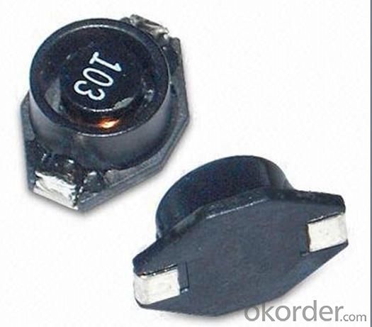
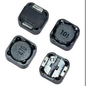
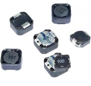
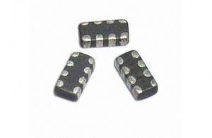
PBP Series Shielded SMD Power Inductor
- Ref Price:
-

- Loading Port:
- China Main Port
- Payment Terms:
- TT or LC
- Min Order Qty:
- 1000 Pieces pc
- Supply Capability:
- 20,000 Pieces per Day pc/month
OKorder Service Pledge
Quality Product, Order Online Tracking, Timely Delivery
OKorder Financial Service
Credit Rating, Credit Services, Credit Purchasing
You Might Also Like

1. pbp series shielded smd power Inductor
2. Rated current:0.5-10A
3. Inductance0.5~6000uH
4. Quality assured
5. competitive price
smallest possible size and high performance they are with high energy storage
Feartures:
The Surface Mount Inductors are designed for the smallest possible size and high performance,
They are with high energy storage and very low resistance making them the ideal inductors for
DC-DC conversion in the following application.
- Q: a series circuit contains:an AV power source(15v(peak to peak)/1.5 kHz/ 0 Deg)a 100 ohm resistor and a 10mH inductor.Calculate the peak to peak voltage across the resistor and inductor and determine the phase angle for each with reference to input voltage. will be quick to award best answer if it is good quality! :)
- Your question relies upon on the circuit layout. If the two aspects are in parallel then the voltage will equivalent the means furnish by way of fact they're one and a similar. different connections would have a diverse consequence. An inductor shops ac means and releases it back into the circuit throughout the time of each and every ac cycle. while voltage is utilized to an inductor present day flows slowly before each and every thing and then ramps up greater effectively storing means. while the provision voltage is decreased, it releases that saved means performing very similar to yet another means furnish.
- Q: A circuit contains only a(n) 0.179 H inductor. An AC voltage of peak value 176 V andfrequency 61.9 Hz is applied to the circuit.When the instantaneous voltage is 176 V,what is the instantaneous AC current?Answer in units of A
- The phrase 'a(n) 0.179 H inductor' implies a practical electrical component. Such a thing will inevitably have some resistance, and in order to solve the problem we need to know what this resistance is. Since we are told nothing about it we cannot solve the problem. However, if we understand this to be a theoretical problem, and understand the first sentence to mean 'A circuit contains only inductance of 0.179 H' and if we make the further assumption that the applied voltage is sinusoidal, we can say that the current will be zero at the instant that the voltage is at its peak value. This is because the voltage and current will be 90deg out of phase in a purely inductive circuit, or in relation to a pure inductance. Note that I have had to re-phrase the question, and make an assumption about the nature of the applied voltage in order to answer the question. My answer should not be taken as the correct answer to the problem as stated. That problem is insoluble.
- Q: As inductor prevents the abrupt change of current so when dc current pass through the inductor there creates the rate of change of current.as well as rate of change of flux.so emf produced but this happen only for 5* time constant.after that there is no change of dc current inside the inductor and it acts a short circuit.so no emf produced.so why inductor at DC current acts as a open circuit at initial time and later as short circuit???
- Try thinking of an inductor working with current the same way a big water wheel would act with a channel of water. At first the wheel's mass prevents it turning if there is a difference in water levels (voltage) on each side. Then it begins to turn and gradually speeds up until eventually it is turning almost as fast as the water itself is moving. At this point there is no difference in water level on either side on the wheel. The analogy is surprisingly close and this is because each has quantity that is reluctant to change. The key is that it is only reluctant, it doesn't refuse outright. So despite not changing its state instantly, like a resister, an inductor (or water wheel) does still begin to change even from the start. If the input conditions then remain static, then the inductor/wheel will eventually catch up (or get close enough anyway) and cease to provide any impediment to current at all.
- Q: a detailed answer required. can inductors also be used or is there some drawback associated with them
- Yes, inductors could also be used. For instance an inductor can perform integration: I (1/L)integral(V dt); as well as differentiation: V L di/dt . I'm thinking that there are maybe two reasons why we use RC integrators and differentiators instead of RL. This is my opinion only but it's based on many years of experience. First is that capacitors of a very wide range of values are easily obtained. Not so for inductors. If you're an electronics hobbyist or even an engineering lab for a large company, you will have lots more capacitors in stock than inductors. This has been true anywhere that I've ever worked. The right value capacitor is easy to get compared to the right value inductor. Second (and probably less important than the first reason) is that in many active integrator/differentiator circuits, it may be desirable to isolate the DC operating voltage of one stage from another, especially when operating from a single supply. Can't do this with an inductor. Other than that, I don't know. I guess that's just the way it is.
- Q: An inductor of 170 turns has a radius of 8 cm and a length or 30 cm. The permeability of free space is 1.25664 x 10^-6 N/A^2.Find the energy stored in it when the current is 0.6 A.
- Inductance of a solenoid, air L ??N?A/Ln Ln is length in meters A is area in meters? N is number of turns ?? is the magnetic constant 1.2566×10?6?H/m (or T·m/A) use the above formula to calculate inductance. Change units to meters. then use E ?LI? Energy in an inductor to get the energy. .
- Q: 1 )an inductor connected to a dc source, amount of current flow depends ona) dc resistance b) reactance c) inductance2) an inductor in a circuit opposes a) starting current b) stopping current c) AC d) all of the above3) Placing an inductor in series with a lamp that is connected to AC souce wll cause the lamp toa)glow brighter b) burn out c) glow dimmer d) overload the sourceDc resistance of an an inductor is always equal to the inductors reactance. True or falseDc resistance and reactance of an inductor have very different effecs in an AC circuit. True or falsewhen dc is applied to an inductor only the inductor's reactance affcts current flow. True/ False
- 1.)c 2.)b 3.)c false true false
- Q: if i have coupled inductors with mutual inductance M ,how would i go about replacing them with 1 equivilant inductor and what would be its value ?
- An equivalent single X value for the two initial inductances X1and X2, having mutual inductance M, very much depends on how X1 and X2 are connected into a circuit and upon how X is to be connected. There is not a unique answer independent of circuit connection.
- Q: 2.Two 0.20-H inductors and one 0.44-H inductor are connected in series across the terminals of a 60.0-Hz ac generator. What is the total inductive reactance of this circuit?3. An ac generator supplies an rms (not peak) voltage of 180 V at 60.0 Hz. The generator is connected in series with a 0.50-H inductor, a 6.0-?F capacitor and a 300-Ω resistor a.What is the capacitive reactance? b.What is the rms current through the resistor? 4.A series RCL circuit is comprised of a 3.00-mH inductor and a 5.00-?F capacitor. What is the resonant frequency of this circuit?5.An ac generator supplies an rms (not peak) voltage of 180 V at 60.0 Hz. The generator is connected in series with a 0.50-H inductor, a 6.0-?F capacitor and a 300-Ω resistor. Determine the peak voltage of the generator.6.An ac generator supplies a peak (not rms) voltage of 150 V at 60.0 Hz. The generator is connected in series with a 35-mH inductor, a 45-?F capacitor and an 85-Ω resistor. What is the impedance of the circuit?
- 2.Two 0.20-H inductors and one 0.44-H inductor are connected in series across the terminals of a 60.0-Hz ac generator. What is the total inductive reactance of this circuit? ZL jωL jω(0.2+0.2+0.44) j*2*π*60*(0.2+0.2+0.44) 3. An ac generator supplies an rms (not peak) voltage of 180 V at 60.0 Hz. The generator is connected in series with a 0.50-H inductor, a 6.0-?F capacitor and a 300-Ω resistor a.What is the capacitive reactance? ZC 1/j*2*π*60*C b.What is the rms current through the resistor? I V/Z Z R + j(2*π*60*L - 1/(2*π*60*C) ) 4.A series RCL circuit is comprised of a 3.00-mH inductor and a 5.00-?F capacitor. What is the resonant frequency of this circuit? fo 1/2*π*√L*C) 5.An ac generator supplies an rms (not peak) voltage of 180 V at 60.0 Hz. The generator is connected in series with a 0.50-H inductor, a 6.0-?F capacitor and a 300-Ω resistor. Determine the peak voltage of the generator. Vrms Vpeak/√2) Vpeak √2)*Vrms 6. Z R + j(2*π*60*L - 1/(2*π*60*C) ) Magnitude of Z |Z| √R? + ( 2*π*f*L - 1/2*π*f*C)?] Plug in the values.
- Q: A 4.40-mH inductor is connected to an ac voltage source of 149.5 V rms. If the rms current in the circuit is 0.880 A, what is the frequency of the source?
- X of L 149.5V/.88A 170 Ohm Frequency (X of L) / (2pi)*( L) (170 Ohm)/[(3.14)*(.0044H)] 12,305Hz
- Q: Calculate the impedance of the circuit if the source frequency is 60 Hz and when it is 6.9*10^4 Hz
- R30 x 10^3 ohms L80 x 10^6 henry f60hz omega2(pi)f120(pi) impedence by inductoromega*L impedence by resistorR total impedenceroot of(R(square) + Omega*L(square))
Our products have highest quality and competitive prices.Our well-equipped facilities and excellent quality control throughout all stages of production enable us to guarantee total customer satisfaction. As a result of our high quality products and outstanding customer service, we have gained a global sales network.
1. Manufacturer Overview
| Location | Guangdong,China (Mainland) |
| Year Established | 2010 |
| Annual Output Value | US$10 Million - US$50 Million |
| Main Markets | North America; South America; Eastern Europe; Southeast Asia; Africa; Oceania; Mid East; Eastern Asia; Western Europe |
| Company Certifications | ISO 9001:2000 |
2. Manufacturer Certificates
| a) Certification Name | |
| Range | |
| Reference | |
| Validity Period |
3. Manufacturer Capability
| a) Trade Capacity | |
| Nearest Port | |
| Export Percentage | 41% - 50% |
| No.of Employees in Trade Department | |
| Language Spoken: | |
| b) Factory Information | |
| Factory Size: | |
| No. of Production Lines | |
| Contract Manufacturing | OEM Service Offered Design Service Offered Buyer Label Offered |
| Product Price Range | |
Send your message to us
PBP Series Shielded SMD Power Inductor
- Ref Price:
-
- Loading Port:
- China Main Port
- Payment Terms:
- TT or LC
- Min Order Qty:
- 1000 Pieces pc
- Supply Capability:
- 20,000 Pieces per Day pc/month
OKorder Service Pledge
Quality Product, Order Online Tracking, Timely Delivery
OKorder Financial Service
Credit Rating, Credit Services, Credit Purchasing
Similar products
Hot products


Hot Searches

