
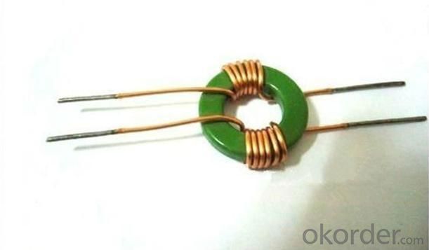
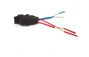
Low Frequency High Quality Coil/Inductor
- Ref Price:
-

- Loading Port:
- China Main Port
- Payment Terms:
- TT or LC
- Min Order Qty:
- 3000 Pieces pc
- Supply Capability:
- 3000 PiePieces per Week pc/month
OKorder Service Pledge
Quality Product, Order Online Tracking, Timely Delivery
OKorder Financial Service
Credit Rating, Credit Services, Credit Purchasing
You Might Also Like

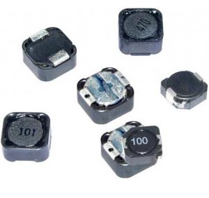
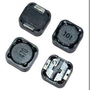
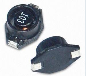
Specifications
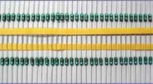
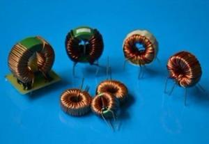
1.Radial Fixed Leaded Inductors with Inductance ranging from 0.30uH to 100mH.
2.ROHS compliance.
3.Good quality and low price
4.low loose
Our products have gained the international certifications, such as CQC, CE, RoHS, UL and so on, from internationally powerful authorities. We have got ISO9001 certificate. We promise to offer the best products to our clients. We look forward to cooperating with all friends for more mutual benefits.
- Q: I always wandered about that.
- The capacitor and inductor do not create oscillations. They require an outside Voltage source to start and sustain oscillations. Edit add on: This is not a nerd rule just simply a fact.
- Q: If a full wave rectification of an A.C. current flows through a closed circuit in series a coil of wire wound around a solenoidal core, what happens to the current in the overall circuit?
- What is the overall circuit? We would need more details to answer this.
- Q: I have a 9 Volt DC source in series with an inductor, and a switch. Once i close the switch, there is a spike on the screen of my oscilloscope but it is not precisely when I close the switch, a very breif moment later. The spike rapidly comes down to a steady line across the screen - indicating the dc source. Once I open the switch I get the reverse situation, the spike is in the negative and increases to the steady state.I am not truly understanding what is going on here. I connected my leads across the coil, negative to the side of the coil connected from the negative battery terminal, the positive to the other end. I am seeing the voltage drop across the coil, as the current increases is this voltage drop increasing to a maximum point then it suddenly returns to a minimum value where the voltage is source? I am soo confused .Help !!
- I suppose coil is inducter you meanthen change of its inductive reactance will determine its change in voltage.since you are having dc source voltage will not change to maximum value when current change to max reason rate of change of current is 0 then. why did you ask 3 times hhhaaahh?
- Q: All the current from the wire before it will go through the inductor because there is no resistance, right?
- Almost. If it is made of very low ohmic value.
- Q: For an ideal conductor in an ac circuit explain why the voltage across the inductor must be zero when the current is at the maximum
- I would answer as i know: From equation V L (di/dt), it tells us something. The nature phenomenon of an ideal or any practical inductor is that it will protect current not to change rapidly.For example, if the current at first condition is 5 Amp. but suddenly you increase it to 6 Amp. the inductor will act aginst the change so it will increase by some amount of time not suddenly increase.The time depend on many factors-induction,etc. At the maximum point of waveform,the current is quite constant.So,it's not nessessary for the inductor to act against the current.The Vol. so would Zero. Does this help?
- Q: Do you think that drill instructors in the marines and Drill Sergeants in the army be allow to hit recruits like during the Vietnam War and before. War is much more cruel then boot camp and if you can't survive a punch to the gut because you made a mistake there how will you survive in war. Also I've heard from my cousins in the marines that Drill instructors will still hit you if you mess up in boot camp when the media isn't around is that true?
- THATs BS Your Cousins LIE! - In Boot - We are NOT your Mother. You have to be MADE into a man, and a lot of boots come from LIB-privilege lives, so we have to change that, because other lives depend on this recruit being a MAN when it's time. That's why BootCamp is 8 weeks (2 months) so we have time to undo what Mommy Daddy did. THEN-Training Nobody Beats recruits, and i take GREAT offense at YOU for using that word. I retired as a drill Instructor from Camp Pendleton, San Diego, CA as a DI after serving in NAM. WE NEVER BEAT recruits!!! Rough them up - Yes, keep them up late get them up early? - YES, Yell scream? YES! - Because Mommy Daddy Didn't teach them RESPECT! Nobody was EVER Beat in any of our Squads, Platoons or Companies EVER! . You can take that to the Bank **** @Al Bundy - FOAD!
- Q: How do you do this problem?Using the expression relating the rate at which current changes in an inductor to the voltage produced at it, find the voltage across the inductor when a switch supplying 6.8 A to a 6.5 mH inductor is suddenly opened. Assume that current drops linearly to zero in 3.4 milliseconds.
- Inductor Equation
- Q: Help out a brother here.The graph below shows the voltage across a 560 mH inductor vs. time
- Since the plot can be separated into piecewise functions, the easiest way is to integrate the functions at the points you need Remember the current across an inductor cannot change instantaneously First off: Voltage across an inductor V L di/dt Rearranging for current i 1/L * [integral from t0 to t chosen] v(t) dt from t0 to t7*10^-6, solving the integral 1/560*10^-3 * [-400t] from t0 to t7 [-400*7*10^-6]/0.56 -5mA Similarly, repeat from t7us to t9us and sum the answers from t7*10^-6 to t9*10^-6, solving the integral 1/560*10^-3 * [320t] from t7*10^-6 to t9*10^-6 [320*9*10^-6 - 320*7*10^-6] / 0.56 1.14 mA Answer: Current at 9us -5mA + 1.14 mA -3.86mA
- Q: A 16.0 mH inductor, with internal resistance of 20.0 ohms, is connected to a 110 V rms source. If the average power dissipated in the circuit is 40.0 W, what is the frequency? (Model the inductor as an ideal inductor in series with a resistor.) ____ HzI keep getting 467 Hz but this is incorrect and have no idea what I am doing wrong. I've tried doing it a bunch of different ways but keep getting lost somewhere along the way.Any suggestions on how to accomplish this problem?
- 1 mH 10^(-3) H current power / voltage 40 W / 110 V 0.3636 Amps voltage Henries * current / time 110 V 1.6 * 10 ^ (-2) H * 0.3636 Amps / time Isolate time: time 1.6 * 10^(-2) H * 0.3636 Amps / 110 V 5.2887 * 10^(-5) seconds frequency inverse of time 1/(5.2887 * 10^(-5)) 18908 Hz I probably made a mistake in there somewhere. I don't remember how to factor in internal resistance or if that's even necessary for this problem.
- Q: antenna ,is it act like an exitation source for loop antenna to generate oscillations.plz answer it
- An inductive coupling link/loop can be used with a loop antenna. This works in the same way as a transformer, with the inductive link as the primary (for transmitting), but at the particular radio frequency. A loop antenna often represents some sort of resonant circuit, and this can be combined with the inductive link coupling to match the antenna impedance to the transmission line and transmitter impedances. With other types of antenna an inductor and/or capacitor arrangement (an LC network) may be used for matching the antenna impedance to the lines. The actual values and conficuration depends on the specific antenna. For example, teh model of a vertical quarter wave antenna is a small capacitor in series with the radiation resistance. By adding a series inductor the capacitance can be made to resonate, maximising the current in the radiation resistance.
Our goods sell very well and gain a good reputation from the clients with our production scale, environmentally friendly products, excellent product quality, first-class enterprise management, the most competitive price and perfect service.Our products have gained the international certifications, such as CQC, CE, RoHS, UL and so on.
1. Manufacturer Overview
| Location | Shenzhen, Guangdong, China (Mainland) |
| Year Established | 2006 |
| Annual Output Value | US$2.5 Million - US$5 Million |
| Main Markets | North America; South America; Eastern Europe; Southeast Asia; Africa; Oceania; Mid East; Eastern Asia; Western Europe; Central America; Northern Europe; Southern Europe; South Asia; Domestic Market |
| Company Certifications | CE Certificates |
2. Manufacturer Certificates
| a) Certification Name | |
| Range | |
| Reference | |
| Validity Period |
3. Manufacturer Capability
| a) Trade Capacity | |
| Nearest Port | Shekou,Yantian |
| Export Percentage | 51% - 60% |
| No.of Employees in Trade Department | 3-5 People |
| Language Spoken: | English, Chinese |
| b) Factory Information | |
| Factory Size: | 3,000-5,000 square meters |
| No. of Production Lines | 9 |
| Contract Manufacturing | OEM Service Offered Design Service Offered Buyer Label Offered |
| Product Price Range | Average |
Send your message to us
Low Frequency High Quality Coil/Inductor
- Ref Price:
-
- Loading Port:
- China Main Port
- Payment Terms:
- TT or LC
- Min Order Qty:
- 3000 Pieces pc
- Supply Capability:
- 3000 PiePieces per Week pc/month
OKorder Service Pledge
Quality Product, Order Online Tracking, Timely Delivery
OKorder Financial Service
Credit Rating, Credit Services, Credit Purchasing
Similar products

Hot products

Hot Searches

