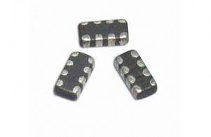
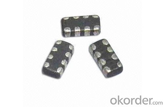
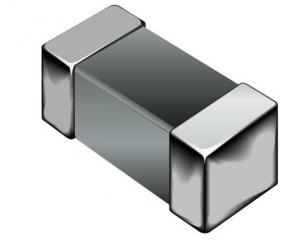
SMD Multilayer Ferrite Chip Bead 0805
- Ref Price:
-

- Loading Port:
- China Main Port
- Payment Terms:
- TT or LC
- Min Order Qty:
- 4000 Pieces pc
- Supply Capability:
- 4000 Pieces per Day pc/month
OKorder Service Pledge
OKorder Financial Service
You Might Also Like

1.SMD multilayer ferrite chip bead
2.High Impedance Characteristics
3.size: 0805
4.RoHs
5.competitive price
Features:
*Low crosstalk/DCR, high reliability
*Low crosstalk between adjacent circuits
*Single MZA series chip provides noise attenuation for four lines, ideal for various highly miniaturized I/D lines
*Internal electrodes feature low DC resistance, minimizing wasteful power consumption
*Electroplated terminal electrodes accommodate flow and reflow soldering
*Mololithic structure ensures high reliability
*Operating temperature range from -25 to 85℃
Applications:
*High-frequency noise counter measured in computer
*Printers
*Portable telephones and other equipments
*VCRs
*Televisions
- Q: Here is the question:Two ideal inductors (.10 H, .50 H) are connected in series to an ac voltage source with amplitude 5.0V and frequency 126 Hz.a) What are the peak voltages across each inductor?b) What is the peak current that flows in the circuit?I know that you use V IXL *L is subscript*.I don't know if you are supposed to use rms in the equation like Vrms Vpeak/1.4 (square root of 2).Any help would be greatly appreciated and showing me the work/equation you are using. I am just generally confused lt;. Thanks a lot.
- If the 'amplitude' is 5v, then that's the peak value. you gotta take the r.m.s value and solve that problem :-)
- Q: I plan on making a 500mH inductor, but I'm not sure how big it needs to be to allow the space for the number of turns it needs with a reasonable size wire. (Reasonable size meaning it is readily available and not so small soldering burns through the wire.)
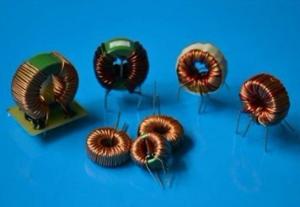
- TOROID CORE HAS DIFFERENT SIZE AND DIFFERENT FERRITE COMBINATION THAT AFFECT THE TURNS RATIO TO INDUCTANCE. THE BEST WAY TO DO IT BY MEASURE THE FINISHED CHOKE WITH AN INDUCTANT METER, AND THEN EITHER ADD OR REDUCE THE TURNS. WIRE SIZE IS THE KEY FACTOR TO DETERMENT ITS CURRENT RATE. 500MH WOULD NOT BE A SMALL TOROID CHOKE, HAS AT LEAST SIZE DIA.1.5 INCHES. TRY AWG#30 1200 TURNS.
- Q: A constant voltage of 4.00 V has been observed over a certain time interval across a 2.20 H inductor. The current through the inductor, measured as 1.00 A at the beginning of the time interval, was observed to increase at a constant rate to a value of 6.00 A at the end of the time interval. How long was this time interval?
- It varieties a transmission line, with incredibly (no imaginary / reactive) impedance. As for a thank you to calculate it, i ought to could desire to airborne dirt and mud off a textbook, or wikipedia 'transmission line thought'. attempt Z_0 sqrt (L / C)
- Q: how to analyze a first order circuit having two inductors (or two capacitors) connected neither in series nor Parallel .I mean what will be the differential equation?.what will be the time constant?Can we convert it into equivalent circuit containing one inductor??if yes,how??Any help will be appreciated.thanks
- You cannot convert a T or Pi type filter into equivalent components and expect the same Q. Those designs aren't to use up excess components in a warehouse somewhere. So, you can build filters that are resonant at the same frequencies with fewer components, but the configuration changes and so do the circuit parameters.
- Q: If an inductor carries 100mA DC of current when connected across a 30V DC source, then what is its resistance?
- I V / R R V / I R 30 / 100e-3 300 ohms The fact that is an inductor does not matter in presence of dc voltage. When non uniform voltage is present then this DC resistance will still be there, but there will be frequency dependent effect as well.
- Q: I want to know what is an ideal series inductor for a storage capacitor connected to a xenon flash tube to preserve flash tube from damage caused by pick current? and how to calculate it for other situation?Is it really precise or I can use any near values? also which type of inductor is better for this?My current capacitor is an electrolyte 1200uF 450V according to flash tube I use.In flash tube datasheet only mentioned to use a series choke after capacitor!
- A flash tube has both a peak current and energy rating. The current through the tube will be a damped sinusoid and the peak value is determine by the inductor. The energy is determined by the cap.
- Q: Cant seem to get my head around this question so any advice would be greatA circuit with an inductor(with both resistance and inductance) Vrl (200+j300)V connected in series to a capacitor c150 micraF across a power supply with a 50Hz supply voltage. The supply current is 25lt;0 degreesCalculatea) impedance of the inductor expressed in complex formb) the values of R and L of the inductorc) the value of the supply voltage, expressed in polar formd) the phase angle of the circuite) the apparent and active powers of the circuitf) draw a scaled argand diagram showing the supply current and all voltages
- Vrl 200 + j 300 Vrl √[200? + j300]? 360.56 Vrms 56.31 degrees R Zr 200 V / 25A 8 Ohm Is 25A 0 degrees Zrl 360.56 Vrms 56.31 degrees / 25 A 0 degrees Zrl 14.42 Ohm 56.31 degrees Zrl 8 Ohm + j12 Ohm f 50Hz C 150 μF Zc -1/2πfC Zc -1/(100π(.00015)) Zc -j21.22 Ohm Zr + Zc Zrc Zr 8 + j00.00 Ohm Zc 0 - j21.22 Ohm Zrc 8 - j21.22 Ohm Zrl - Zrc Zl Zrl 8 + j12.00 Ohm Zrc 8 - j21.22 Ohm Zl 0 + j33.22 Ohm Zl 33.22 Ohm Zl 2 π f L L Zl/ 2 π f 33.22 Ohm /(100 x π) .105743 L 105.743 mH Zt Zr + Zl + Zc Zr 8 + j00.00 Ohm Zc 0 - j21.22 Ohm Zl 0 + j33.22 Ohm Zt 8 + j12.00 Ohm Zt 14.42 56.31 degrees Is 25A 0 degrees Vt (14.42 56.31) x (25A 0) 360.5 Vrms 56.31 degrees Pt 360.5 Vrms 56.31 degrees x 25A 0 degrees 9012.5 56.31 W Is? 25A? 0 degrees 625 A? 0 Pr 8 Ohm x 625A? 5000 W Pc - j21.22 Ohm x 625A? -13262.5 VAR Pl j33.22 Ohm x 625A? 20762.5 VAR Pt 5000 W + 7500 VAR Pt 9013.9 VA 56.31 degrees a) impedance of the inductor expressed in complex form Zl 0 Ohm + 33.22 j Ohm b) the values of R and L of the inductor R Zr 200 V / 25A 8 Ohm L 105.743 mH c) the value of the supply voltage, expressed in polar form Vt (14.42 56.31) x (25A 0) 360.5 Vrms 56.31 degrees d) the phase angle of the circuit φ 56.31 degrees e) the apparent and active powers of the circuit Pr 8 x 625A? 5000 W Pt 5000 W + 7500 VAR Pt 9013.9 VA 56.31 degrees f) draw a scaled argand diagram showing the supply current and all voltages Let me goI won't make itYou go on ahead without me :)
- Q: An inductor in the form of a solenoid contains 400 turns, is 15.0 cm in length, and has a cross-sectional area of 3 cm2. What uniform rate of decrease of current through the inductor induces an emf of 175 ?V?
- EMF - dΦ/dt -μ?NA/L (di/dt) di/dt - (1.75x10^-4)(0.15) / (4π×10^-7)(400)(3x10^-4) - 174 Amp/sec
- Q: An electric oscillator is made with a 0.10 uF capacitor and a 1.0 mH inductor. The capacitor is initially charged to 5.0 V.
- This may be an overly long method and an incorrect interpretation of the question but assuming it is an inductor and capacitor in parallel: Impedance of inductor 2πfL and imp. of capacitor 1 / (2πfC) When the current resonates the impedances are equal and thus this equation is formed: 1 / (2π√(RC)) f, the resonant frequency. So you calculate the frequency and that allows you to get the impedance of the inductor or capacitor - which turns out to be 100 ohms. In parallel two 100 ohm components give an impedance of 50 ohms (1 / R 1 / R1 + 1 / R2). Therefore the maximum current should be 5V / 50? 0.1 A
- Q: A 9.5 H inductor carries a current of 1.8 A. At what rate must the current be changed to produce a 60 V emf in the inductor?
- emf for inductor: emf L(di/dt) 60 9.5 (di/dt) (di/dt) 6.32 A/s
1. Manufacturer Overview
| Location | Guangdong,China (Mainland) |
| Year Established | 2010 |
| Annual Output Value | US$10 Million - US$50 Million |
| Main Markets | North America; South America; Eastern Europe; Southeast Asia; Africa; Oceania; Mid East; Eastern Asia; Western Europe |
| Company Certifications | ISO 9001:2000 |
2. Manufacturer Certificates
| a) Certification Name | |
| Range | |
| Reference | |
| Validity Period |
3. Manufacturer Capability
| a) Trade Capacity | |
| Nearest Port | |
| Export Percentage | 41% - 50% |
| No.of Employees in Trade Department | |
| Language Spoken: | |
| b) Factory Information | |
| Factory Size: | |
| No. of Production Lines | |
| Contract Manufacturing | OEM Service Offered Design Service Offered Buyer Label Offered |
| Product Price Range | |
Send your message to us
SMD Multilayer Ferrite Chip Bead 0805
- Ref Price:
-
- Loading Port:
- China Main Port
- Payment Terms:
- TT or LC
- Min Order Qty:
- 4000 Pieces pc
- Supply Capability:
- 4000 Pieces per Day pc/month
OKorder Service Pledge
OKorder Financial Service
Similar products
Hot products

Hot Searches
Related keywords

