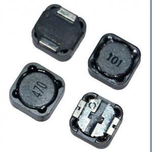
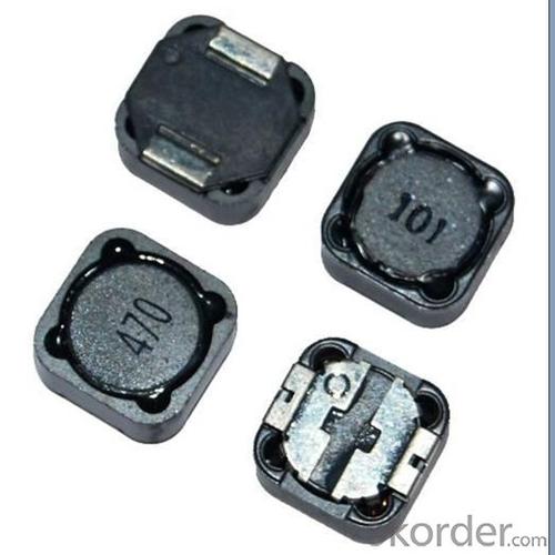
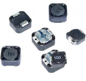
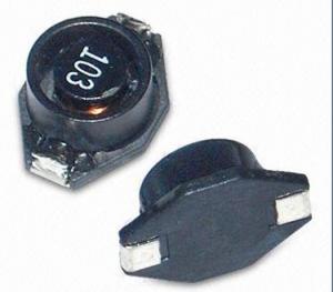
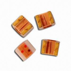
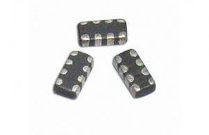
PBH Series SMD Power Inductor
- Ref Price:
-

- Loading Port:
- China Main Port
- Payment Terms:
- TT or LC
- Min Order Qty:
- 1000 Pieces pc
- Supply Capability:
- 20,000 Pieces per Day pc/month
OKorder Service Pledge
OKorder Financial Service
You Might Also Like

1. pbh series smd power inductor
2. Rated current: 1-10A
3. Inductance0.5~6000uH
4. ROHS
5. competitive price
Features:
1.SMD Power Inductor
2.Magnetic shieled surface mount inductor with high current rabing low D.C resistance
3.Excellent terminal strength
4.Packed in embossed carrier tape and can beused by automatic mounting machine.
5.Various hogh power inductors are superior to be high saturation for suiface mounting.
Applications:
Power supplu for VTR,OA equipment Digital camera, LCD television set notebook PC,
portable communication equip,ents, DC/DC converters, etc.
- Q: and whyalso does that work when you open circiut a capacitor.
- Remember that when a component is shorted, the situation is effectively the same thing as taking a wire from one terminal of the component to the other. That is, it's like having a wire in parallel with the component itself. Current flows through the short (or wire) instead of through the component. This is as true in AC circuits as it is in DC circuits. So if an inductor (or any other component) is shorted, then any component in parallel with it will also be shorted because it will also not have any current flowing through it. Components in series will not be shorted provided the short starts at one of the inductor's terminals and ends the other.
- Q: An LC circuit consists of a capacitor, C 1.72 μF, and an inductor, L 5.32 mH. The capacitor is fully charged using a battery and then connected to the inductor. An oscilloscope is used to measure the frequency of the oscillations in the circuit. Next, the circuit is opened, and a resistor, R, is inserted in series with the inductor and the capacitor. The capacitor is again fully charged using the same battery and then connected to the circuit. The angular frequency of the damped oscillations in the RLC circuit is found to be 19.5% less than the angular frequency of the oscillations in the LC circuit. a) Determine the resistance of the resistor. b) How long after the capacitor is reconnected in the circuit will the amplitude of the damped current through the circuit be 19.0% of the initial amplitude? c) How many complete damped oscillations will have occurred in that time?
- We know Wo 1/sqrt(LC) 10,454 rad/s Wd is given to be 0.805*Wo Looking at the reference alpha^2 Wo^2 - Wd^2 and Wd 0.805*Wo alpha^2 Wo^2(1-0.805^2)38,465,981 alpha 6202.1 R/2L R 66 Ohms b) we can write 0.19 e^(-6202.1*t) Ln(0.19)/(-6202.1) t 0.268 milliseconds c) wd 8415.5 2pi/T T 0.747ms So it appears the current is at 19% before even one oscillation has finished unless I have an error. In an RLC ckt when the charged cap is connected, i(0) 0 All of the voltage is dropped across the inductor meaning VR0 at t0 which means i(0) 0 So not sure what initial amplitude they are talking about
- Q: Building a BFO metal detectorReference coils calls for,AWG #30dimensions: 50 mm height x .5 mm width120 turnsI'll be using AWG #24. However, AWG #24 is .5 mm in diameter. If you do the math, that's120 turns x .5 mm 60 mmSo my coil will be 60 mm. THAT'S NOT WHAT THE ENGINEER CALLS FOR. I'm 10 mm too long, therefore I have an extra 20 winds (10 mm of 24 awg 20 winds)CAN I OVERLAP?Problem is the reference coil (this coil) is fitted into a water fitting. The water fitting is threaded on the outside fitted with a nut. When you move the nut up down the water fitting, it changes the frequencyWon't this be an issue?THanks
- Capacitors and inductors within the circuit will make the viberations at desired frequency to drift at slash resistance than different (undesired) vibrations. As a consequence reducing the noises in reception. Variable capacitors are exceptional to high-quality tune your stations. However the added circuitry will mean more vigor requirement which defies use of the term 'easy Radio'
- Q: I am trying to understand how an inductive sensor works. I have the circuit diagram for a filter amplifier circuit. However I have an inductor and capacitor in parallel with eachother. I don't think it is to do with resonance because the inductor is being induced with a voltage using an electomagnet. Can anyone help with this??
- It can be a very sharp filter to amplify only a narrow band of frequencies, determined by the resonant frequency of the LC. .
- Q: An inductor has a 54.0Ohms reactance at 60.0 Hz. What willbe the maximum current if this inductor is connected to a50.0-Hz source that produces a 100-V rms voltage?
- xc 1/jwc v rms 1/ root(v)
- Q: If ig(t) 0.5 cos 2000t A, find the average power absorbed by each element ((a) 130-Ω resistor, (b) 40-Ω resistor, (c) source, (d) inductor, (e) capacitor) in the circuit in the figure below.
- Let's just go through it the straight way. You know, from your source, that: ? ? ? ? ω 2000 ? ? ? ? Ip ?A, ∴ Irms Ip ? (√2) You can compute the reactance of your capacitor (C12.5μF) and inductor (L60mH) as: ? ? ? ? XC 1 ? (ω?C) 40?, ∴ Z?C -40j ? ? ? ? XL ω?L 120?, ∴ Z?L 120j Let's say that: ? ? ? ? R? 130? ? ? ? ? R? 40? You have two parallel legs, each with a series pair of devices. The total impedance is in the capacitive leg is: ? ? ? ? Z? R? + Z?C 130 - 40j, ∴ |Z?| 10√185 In the inductive leg it is: ? ? ? ? Z? R? + Z?L 40 + 120j, ∴ |Z?| 40√10 So the total parallel impedance of these two legs is: ? ? ? ? Ztot Z??Z? ? (Z? + Z?) 200?(141 + 79j) ? 353 ? ? ? ? ∴ |Ztot| ≈ 91.57112 You know that: ? ? ? ? Vrms Irms ? |Ztot| ? ? ? ? Irms? Irms ? |Ztot| / |Z?| ? ? ? ? Irms? Irms ? |Ztot| / |Z?| ? ? ? ? P? Irms???R? (Irms ? |Ztot| / |Z?|)? ? R? 7??????? W ≈ 7.365 W ? ? ? ? P? Irms???R? (Irms ? |Ztot| / |Z?|)? ? R? 2??????? W ≈ 2.620 W ? ? ? ? Ptot P? + P? 9??????? W ≈ 9.986 W Real power isn't dissipated in ideal capacitors or inductors, so (a) ≈ 7.365 W, (b) ≈ 2.620 W, (c) ≈ 9.986 W, (d) 0 W, and (e) 0 W. Since the problem you show doesn't illustrate VAR units on it, I don't think (d) and (e) should use reactive power. ? ? ? ? P? Irms???R? (Irms ? |Ztot| / |Z?|)? ? R? 7??????? W ≈ 7.365 W ? ? ? ? P? Irms???R? (Irms ? |Ztot| / |Z?|)? ? R? 2??????? W ≈ 2.620 W The above was validated with Spice.
- Q: A 20.0 uF capacitor is charged by a 170.0 V power supply, then disconnected from the power and connected in series with a 0.270 mH inductor.
- The natural (radian) frequency of oscillation is: ω 1/sqrt(L*C) 1/sqrt(270*10^-6 * 20*10^-6) 13.61*10^3 radian/sec At the start of the transient, the inductor current is zero, and all of the energy is stored as electric field energy in the capacitor. The current in the inductor will be sinusoidal with zero crossings at every N*π where N 0, 1, 2, 3 The angle of the sinusoidal inductor current at 1.40ms is: θ ω*t 13.61*10^3 * 1.4*10^-3 19.05 radians Divide this by 2*π to find out how many complete periods are included in the 19.05 radians: N 19.05/(2*π) 3.03 This is probably close enough to 3 complete periods of the inductor current to conclude that for practical purposes, all of the energy has been returned to the capacitor, and only a very small amount of energy (within the significant figures of the component values given) would be in the inductor. I'd answer: approximately zero
- Q: guys can u please explain me how to measure the inductance of a sinusoidal air core inductor ,please explain me with a example,please help me guys!!!!
- There are capacitance meters available and some meters have them built in. You might trying looking on OKorder.
- Q: i cant connect the resistor and inductor and the voltmeter check this
- If you learn to spell and punctuate someone may help you. Yes, it does matter. I would never hire someone who sent me a message like yours.
- Q: If the voltage waveform is applied across the terminals of a 5-H inductor, calculate the current through the inductor. Assume i(0) -1A.
- since t 0.use equation I(t) Im * e ^ (-tR/L) if it sdischarging or if its charging, replace (e^(-tR/L)) with (1-e^(-tR/L)). It depends on the circuit though
1. Manufacturer Overview
| Location | Guangdong,China (Mainland) |
| Year Established | 2010 |
| Annual Output Value | US$10 Million - US$50 Million |
| Main Markets | North America; South America; Eastern Europe; Southeast Asia; Africa; Oceania; Mid East; Eastern Asia; Western Europe |
| Company Certifications | ISO 9001:2000 |
2. Manufacturer Certificates
| a) Certification Name | |
| Range | |
| Reference | |
| Validity Period |
3. Manufacturer Capability
| a) Trade Capacity | |
| Nearest Port | |
| Export Percentage | 41% - 50% |
| No.of Employees in Trade Department | |
| Language Spoken: | |
| b) Factory Information | |
| Factory Size: | |
| No. of Production Lines | |
| Contract Manufacturing | OEM Service Offered Design Service Offered Buyer Label Offered |
| Product Price Range | |
Send your message to us
PBH Series SMD Power Inductor
- Ref Price:
-
- Loading Port:
- China Main Port
- Payment Terms:
- TT or LC
- Min Order Qty:
- 1000 Pieces pc
- Supply Capability:
- 20,000 Pieces per Day pc/month
OKorder Service Pledge
OKorder Financial Service
Similar products
Hot products


Hot Searches

