
Low Frequency Cheap Filter/Iductor
- Ref Price:
-

- Loading Port:
- China Main Port
- Payment Terms:
- TT or LC
- Min Order Qty:
- 1000 Pieces pc
- Supply Capability:
- 10000 Pieces per Month pc/month
OKorder Service Pledge
OKorder Financial Service
You Might Also Like

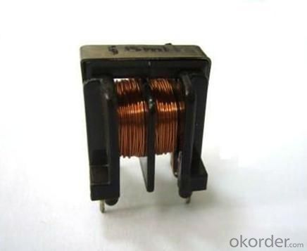
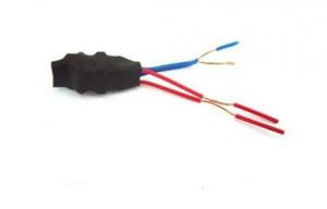
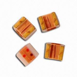
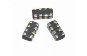
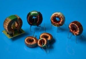
*low frequency Inductor/filter
*High power storage
*Easy insertion,low loose
*Used in various electronic and industry products
|
Our products have gained the international certifications, such as CQC, CE, RoHS, UL and so on, from internationally powerful authorities. We have got ISO9001 certificate.We promise to offer the best products to our clients. We look forward to cooperating with all friends for more mutual benefits.
- Q: For the circuit shown in the figure, the switch has been open for a very long time. (a) What is the potential drop across the 15.0-mH inductor just after closing the switch? (b) What is the potential drop across the 70.0-?F capacitor after the switch has been closed for a very long time?
- An inductor is an open circuit at t0 and a short circuit at t∞. A capacitor is a short circuit at t0 and an open circuit at t∞. That makes things very easy. (a) At t0, all you have is a 75? in series with a 25? resistor. So the voltage on the bottom side of the 15mH inductor is +200V????????? +50V. There is no current in the 50? resistor, so no voltage drop, so the other side of the 15mH inductor is at +200V. So the voltage across the inductor is 150V at t0. (b) At t∞, all you have now is a 50? in series with a 25? resistor. So the voltage on the bottom side of the 70μF capacitor (there is no current in the 38? resistor) is +200V????????? +66?V. The voltage on the other side of the 70μF capacitor is +200V. So the voltage across the capacitor is 133? V at t∞.
- Q: I am supposed to use a 10uH inductor but accidentally ordered a 100uh. How will this effect the circuit?
- It depends what the circuit is intended to do. We need to know more about the circuit to answer this.
- Q: An RLC circuit has a 400 ohm resistance a 2.5 mH inductor and a capacitor. If the circuit is in resonance at 30kHz and is attached to a 20mVrms power supply, what is the power dissipated by the circuit?
- At resonance +jXL -jXC, therefore Z R +jXL -jXC R 400 ohms, since the reactances canel out. The power is only disspiated in the 400 ohm resistor, so P V^2 / R P (0.020V)^2 / 400 P 1E-6 Watt P 1 microWatt ~~~~~~~~~~~~~~~~~~~~~~~~~~~~~~~~~~~~~~~ EXTRA CREDIT The capacitor value for resonance with the 2.5 mH inductor at the frequency of 30 KHz will be f 1 / (2 * pi * SQRT (L * C) ) 30E3 Hz 1 / (2 * 3.1415 * SQRT (2.5E-3 H * C) ) 2 * 3.1415 * SQRT (2.5E-3 H * C) 1 / 30E3 Hz SQRT (2.5E-3 H * C) 5.3052E-6 (2.5E-3 H * C) (5.3052E-6)^2 2.5E-3 H * C 28.1448E-12 C 11.2579E-9 F C 0.0112579 microFarads (uF) 11.2579 nanoFarads (nF) 11,257.9 picoFarads (pF)
- Q: Can a capacitor discharge itself through an ideal inductor ? If yes state the reason , if No how will the charge on the capacitor will behave ?
- A charged perfect capacitor connected to a perfect inductor will have an oscillating voltage: discharge to 0, recharge to initial charge value with opposite polarity, back to 0, etc. forever. This is a sinusoidal oscillation which takes place at a frequency 1/sqrt(LC) rad/s. The reason for the oscillation is explained in the ref., which discusses such a circuit with added resistance. The resistance absorbs energy and causes the oscillation to damp out over time, but the behavior of the capacitor and inductor are the same without resistance.
- Q: A constant voltage of 12.00 V has been observed over a certain time interval across a 2.60 H inductor. The current through the inductor, measured as 3.00 A at the beginning of the time interval, was observed to increase at a constant rate to a value of 7.00 A at the end of the time interval. How long was this time interval?
- Given v12.00V, L2.60H, Δi4.00A The voltage across an inductor is given by: v L*di/dt v L*Δi/Δt Δt (L/v)Δi 0.87s
- Q: A)transformerB)inductorC)resistor
- None of these STORE energy on their own. Is this a serious question?
- Q: After the switch in the following circuit has been closed for a long time (tinfinity), what is the current through L1?Also, after the switch in the circuit in the circuit has been open for t500 microseconds, what's the current through L2?How do i find the current? Please show me or give me instructions how as this will help me in the future.
- The current through L1 and L2 after S1 has been closed a long time is 20 milliamps, (10v/ 500 Ω). 10 (L1 + L2) di/dt + (R1 || R2)i 10 0.250(di/dt) + 500i When S1 is opened 10 0.250(di/dt) + 1,000i with i initial 20 milliamps i 10(e^-t/τ) +10 milliamps where τ L/R 250 millihenry/1,000 250 microsecond after 500 microseconds which is 2 τ i 10e^-2 + 10 1.35 + 10 13.5 milliamps
- Q: A 25.0-mH inductor, a 2.00-μF capacitor, and a certain resistor are connected in series across an ac voltage source at 1000 Hz. If the impedance of this circuit is 200 Ω, what is the value of the resistor? a. 200 Ω b. 552 Ω c. 184 Ω d. 100 Ω e. 579 Ω
- Z sqrt [(Xl - Xc)^2 + R^2] w 1000*2*pi 6280 Xl Lw 157 ohms Xc 1/(C*6280) 79.61 ohms so 200 sqrt[(157 - 79.61)^2 + R^2] on solving we get R 184 ohms
- Q: I want to find the total impendance of a coil. I think I know how to do it but I'm not sure.Z X + RX 2(pi)wLL (uAN^2)/lZ is impendance, R is resistance of the wire of the coil, X is the reactance, w is current frequency in hertz, L is inductance, u is permeability of the core, A is area of the coil loops, N is number of turns in coil, and l is the length of the coil.Together this would yieldZ (2(pi)wuAN^2)/l + RWould this be correct?
- All these formulas only apply to a sine wave single frequency. Z is from ohms law if you have measured V and I: Z + V/I Ideally Z is stated as a vector |Z|, which means a magnitude in ohms and a phase angle in degrees. If X and R are known: Z + sqrt(R^2 + X^2). This is using trigonometry to account for the resulting direction of the vector (phase angle) of the two components R and X. Some calculations involving power, voltage, impedance and current are easier using vectors and trigonometry, while others are easier using complex numbers (real and imaginary component). Complex numbers have a set of rules for arithmetic using them. Adding them as for two impedances in series is very straight forward. Z as a complex number is R + jX The following formulas allow for converting from one representation to the other. PF (Power factor) true power / apparent power cos(θ) from trig. θ arccos(PF) |Z| V / I with a phase angle (θ) Rseries |Z| cos(θ) Xseries |Z| sin(θ) Z R + jX |Z| sqrt(R^2 + X^2) where X is the net reactance of XL and Xc. θ arctan(Xs / Rs)
- Q: I know the resonant frequency is 1/sqrt(LC) and quality factor (1/r)(sqrt(L/C)) and I can use these to calculate my component values with a given resonant frequency, but every inductor has a resistance. How do I account for that in my design?Thank you in advance!
- Using thick wire and ferrite core to make inductor that eliminate internal resistance as small as possible. The wire resistance could be as small as 0.5 ohm that would not affect too much to you design. If not, add its resistance to your calculation.
1. Manufacturer Overview
| Location | Shenzhen, Guangdong, China (Mainland) |
| Year Established | 2006 |
| Annual Output Value | US$2.5 Million - US$5 Million |
| Main Markets | North America; South America; Eastern Europe; Southeast Asia; Africa; Oceania; Mid East; Eastern Asia; Western Europe; Central America; Northern Europe; Southern Europe; South Asia; Domestic Market |
| Company Certifications | CE Certificates |
2. Manufacturer Certificates
| a) Certification Name | |
| Range | |
| Reference | |
| Validity Period |
3. Manufacturer Capability
| a) Trade Capacity | |
| Nearest Port | Shekou,Yantian |
| Export Percentage | 51% - 60% |
| No.of Employees in Trade Department | 3-5 People |
| Language Spoken: | English, Chinese |
| b) Factory Information | |
| Factory Size: | 3,000-5,000 square meters |
| No. of Production Lines | 9 |
| Contract Manufacturing | OEM Service Offered Design Service Offered Buyer Label Offered |
| Product Price Range | Average |
Send your message to us
Low Frequency Cheap Filter/Iductor
- Ref Price:
-
- Loading Port:
- China Main Port
- Payment Terms:
- TT or LC
- Min Order Qty:
- 1000 Pieces pc
- Supply Capability:
- 10000 Pieces per Month pc/month
OKorder Service Pledge
OKorder Financial Service
Similar products

Hot products
Hot Searches

