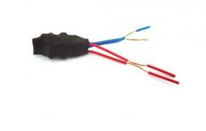

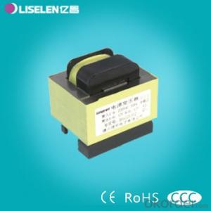
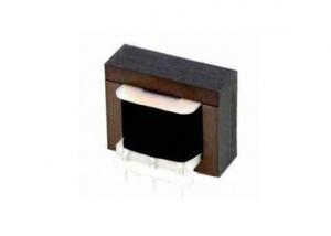
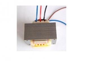
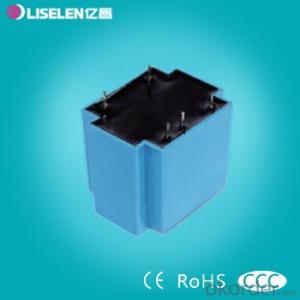
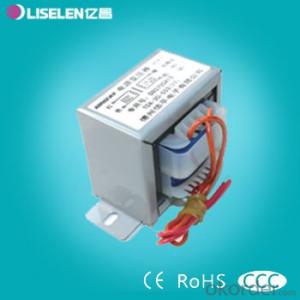
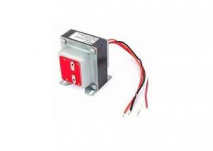
Low Frequency Electronic Transformer
- Ref Price:
-

- Loading Port:
- China Main Port
- Payment Terms:
- TT or LC
- Min Order Qty:
- 800 Pieces pc
- Supply Capability:
- 10000 Pieces per Month pc/month
OKorder Service Pledge
OKorder Financial Service
You Might Also Like

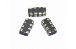
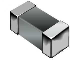
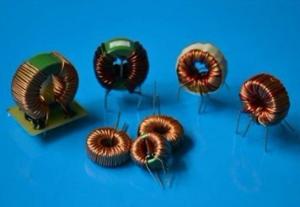
*Electric power Inductor
*High power storage
*Easy insertion,low price
*Used in various electronic and industry products
Our products have gained the international certifications, such as CQC, CE, RoHS, UL and so on, from internationally powerful authorities. We have got ISO9001 certificate. We promise to offer the best products to our clients.We look forward to cooperating with all friends for more mutual benefits. |
- Q: I'm building a circuit in a program called Cadence and the inductor has a little circle on one side of it but not on the other. So does the inductor have a direction? Should the part with the circle be connected to the voltage source or should the other side be connected to it?
- inductors do not have polarity. .
- Q: I have a 9 Volt DC source in series with an inductor, and a switch. Once i close the switch, there is a spike on the screen of my oscilloscope but it is not precisely when I close the switch, a very breif moment later. The spike rapidly comes down to a steady line across the screen - indicating the dc source. Once I open the switch I get the reverse situation, the spike is in the negative and increases to the steady state.I am not truly understanding what is going on here. I connected my leads across the coil, negative to the side of the coil connected from the negative battery terminal, the positive to the other end. I am seeing the voltage drop across the coil, as the current increases is this voltage drop increasing to a maximum point then it suddenly returns to a minimum value where the voltage is source? I am soo confused .Help !!
- Inductors inherently oppose changes in current. The way they do that is to induce a voltage, opposite in polarity with the applied voltage, in an attempt to keep the current the same. So you will get a spike of voltage when you apply power to the circuit, which is for a brief moment of time, stabilizing the current through the inductor. The value of the inductor will dictate the time in seconds, that the inductor will oppose the change in current. The bigger the inductor value, the more time it takes for the inductor to accept the change in current. Once the transients die off, the spike will die, and the inductor will accept its new current flow. This happens almost like a capacitor charging, but opposite.
- Q: If you double the current through an inductor, what happens to the inductance of the inductor?It is doubled.It remains the same.It is halved.
- It remains the same.
- Q: An inductor (L 400 mH), a capacitor (C 4.43 ?F), and a resistor (R 500 ) are connected in series. A 42.0 Hz AC generator connected in series to these elements produces a maximum current of 200 mA in the circuit. (a) Calculate the required maximum voltage ΔVmax.?______ V. (b) Determine the phase angle by which the current leads or lags the applied voltage. The current leads or lags? the voltage by? _____ degrees.
- The reactance of the inductor is XL2 * Pi * f * L XL 2 * 3.1416 * 42 * 0.4 XL 105.55776 ohms The reactance of the capacitor is XC 1 / (2 * Pi * f * C) XC 1 / (2 * 3.1416 * 42 * 0.00000443) XC 855.3938 ohms The total reactance of the circuit is X XL - XC X 105.55776 - 855.3938 X - 749.83604 ohms The reactance is actually 749.83604 ohms. The minus sign indicates the power factor is a leading power factor. The impedance of the circuit is Z - Sqrt(R^2 + X^2) Z Sqrt(500^2 + 749.83604^2) Z Sqrt(812254.08688) Z 901.2514 ohms The voltage to produce 200 mA in the circuit is E I * Z E 0.2 * 901.2514 E 180.25 V (This is RMS voltage) The peak voltage will be E / 0.707 180.25 / 0.707 254.95 V The power factor of the circuit is PF R / Z PF 500 / 901.2514 PF 0.554784 leading The phase angle is the angle having a cosine value of 0.554784. This is 56.30415 degrees. I suggest you check my calculations. TexMav
- Q: A 25.0-mH inductor, a 2.00-μF capacitor, and a certain resistor are connected in series across an ac voltage source at 1000 Hz. If the impedance of this circuit is 200 Ω, what is the value of the resistor? a. 200 Ω b. 552 Ω c. 184 Ω d. 100 Ω e. 579 Ω
- 25 mH Inductor 0.025 H inductor Xl 2 * pi * freq * L j157.0796 2.0uF Capacitor Xc 1 / (2 * pi * freq * C) -j79.5775 Xl + Xc j77.5022 77.5022 @ 90 degrees Since Z^2 R^2 + X^2 Z SQRT ( R^2 + (Xl - Xc)^2 ) with the total impedance as 200 ohms, the resistor is 200 SQRT ( R - 77.5022) 184.3730 ohms (b) 184 ohms
- Q: A voltage of 240 V at 50 Hz applied to an inductor yields a current of 4 A. calculate the maximum stored energy during a cycle, and the average power.is the maximum stored energy 0 or 1.52 ?
- Assuming the current is 4 amps RMS the impedance is j60 ohms, so the inductance is .191 H. The peak current is 1.414*47.07 amps The peak store energy is .5 L Ip^24.77 joules. There is 0 average power consumed by a lossless inductor.
- Q: A 1E-6 F capacitor has a charge of 10.0 microC. It is connected to a 1.0 H inductor at t 0. What is the potential energy of the capacitor and the potential energy of the inductor at t 1 second?
- The angular velocity (omega) here sqrt(1/LC) sqrt(1/(1x10^-6*1) 1000 rad/s Q0 10^x10^-6C Now the charge on a capacitor in an LC oscillator q Q0*cos(omega*t) 10.x10^-6*cos(1000*1) 5.62x10^-6C So the energy q^2/2C (5.62x10^-6)^2/(2*1x10^-6) 1.58x10^-5J Now the current i -omega*Q0*sin(omega*t) -1000*10x10^-6*sin(1000) -0.00827A Energy in an inductor 1/2*l*i^2 1/2*1.0*(0.00827)^2 3.42x10^-5J
- Q: An L ? C circuit contains a single inductor in parallel with a single capacitor. The inductor has an inductance of 0.55 mH and the circuit has a resonant frequency of 250 kHz. What is the capacitance of the capacitor? I keep getting 2.9e-8, but the correct answer is 7.4e-10, and I have no idea why.
- Fr 1 / ((2 x pi) x (sq.rt.(L x C))) sq.rt. (L x C) 1 / ((2 x pi) x Fr) [square both sides of the equation] L x C 1 / ((2 x pi)^2 x (Fr)^2) Solve for C, C 1 / ((2 x pi)^2 x (Fr)^2 x L) C 1 / (6.28^2 x (2.5x10^5)^2 x 0.55 x 10^-3) C 1 / (39.4384 x 62500000000 x 0.00055) C 7.38 x 10^-10 farads, 0.000,000,000738 farads, or 738 pfd Plug C back into the original equation for Fr and see if you get the expected resonant frequency.
- Q: I need this very badly for my Electronics Project, but unfortunately I still can't find it! What are the defects and testing of Inductors??? Please help! X(
- TESTING INDUCTORS An inductor is a device consisting of one or more windings of wire with or without a magnetic core. Frequent causes of inductor coil failures are shorted turns, open turns, and changes in inductor value. Small power supply transformers are similar in construction to inductors and can be tested with the capacitor-inductor analyzer shown in figure 4-30. Inductors may be tested in the circuit, but the circuit impedance will have some effect on the readings. It is recommended that you remove the inductor or transformer from the circuit before you perform any tests.
- Q: A 33.0-mH inductor has a reactance of 2.20 kΩ. (a) What is the frequency of the ac current that passes through the inductor?(b) What is the capacitance of a capacitor that has the same reactance at this frequency?(c) The frequency is tripled, so that the reactances of the inductor and capacitor are no longer equal. What is the new reactance of the inductor?(d) What is the new reactance of the capacitor?I've been stuck on this physics problem. Please Help!! Thanks so much!!
- 2200 Ohms 2 Pi (f Hz) (0.033 Henry), thus f 10610 Hz 2200 Ohms 1 / (2 Pi (10610 Hz) (C Farad)), thus C 6.818 nF Continue with these two relationships to answer (c) and (d)
1. Manufacturer Overview
| Location | Shenzhen, Guangdong, China (Mainland) |
| Year Established | 2006 |
| Annual Output Value | US$2.5 Million - US$5 Million |
| Main Markets | North America; South America; Eastern Europe; Southeast Asia; Africa; Oceania; Mid East; Eastern Asia; Western Europe; Central America; Northern Europe; Southern Europe; South Asia; Domestic Market |
| Company Certifications | CE Certificates |
2. Manufacturer Certificates
| a) Certification Name | |
| Range | |
| Reference | |
| Validity Period |
3. Manufacturer Capability
| a) Trade Capacity | |
| Nearest Port | Shekou,Yantian |
| Export Percentage | 51% - 60% |
| No.of Employees in Trade Department | 3-5 People |
| Language Spoken: | English, Chinese |
| b) Factory Information | |
| Factory Size: | 3,000-5,000 square meters |
| No. of Production Lines | 9 |
| Contract Manufacturing | OEM Service Offered Design Service Offered Buyer Label Offered |
| Product Price Range | Average |
Send your message to us
Low Frequency Electronic Transformer
- Ref Price:
-
- Loading Port:
- China Main Port
- Payment Terms:
- TT or LC
- Min Order Qty:
- 800 Pieces pc
- Supply Capability:
- 10000 Pieces per Month pc/month
OKorder Service Pledge
OKorder Financial Service
Similar products
Hot products

Hot Searches
Related keywords

